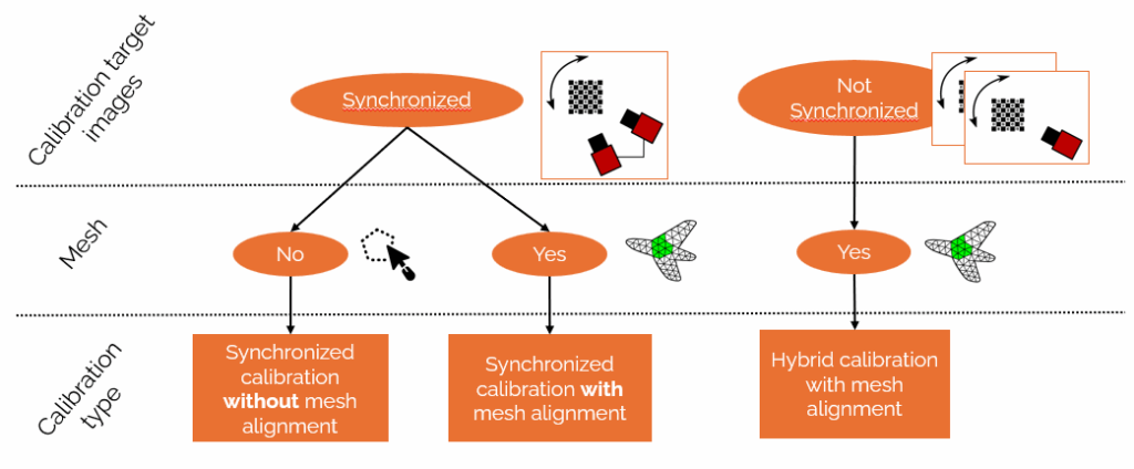
Measurement robustness and the use of “automatic meshing”: focus on synchronized calibration for DIC
Continuing our series of articles on best practices in Digital Image Correlation (DIC), today we present calibration using synchronized target images (with or without mesh alignment), a new procedure that enables the simultaneous determination of intrinsic and extrinsic camera parameters.
This procedure complements the hybrid approach already available in EikoTwin DIC, which remains relevant when camera synchronization is not an option. Here, we describe the principles of this synchronized method, its practical advantages, its procedure and the workflows it subsequently enables in the context of instrumented mechanical testing.
Why synchronized calibration for DIC?
The synchronization of calibration target images ensures ideal geometric consistency between the images captured by the different cameras. It offers several complementary benefits to the hybrid approach already available in EikoTwin DIC, which remains relevant in many situations:
- Enhanced calibration robustness: by imposing a fixed position between the cameras when the test images are taken, this method freezes the relative position of the slave camera in relation to the master camera. This reduces the number of unknown variables when aligning with the EF mesh, thus stabilizing the digital procedure.
- Improved accuracy: by avoiding the measurement bias that can arise when the relative position of cameras is difficult to estimate accurately, particularly in cases where the measurement mesh is close to a plane. This improves the quality of extrinsic matrices and the overall accuracy of 3D reconstruction.
- Possibility of dispensing with finite element mesh alignment: when the aim is simply to carry out displacement and deformation measurements without a test-calculation comparison, this method dispenses with pre-calibration and defines a mesh directly on the image, with a much faster process, obtaining results in less than 3 minutes for simple cases.
Please note: this method requires that the cameras are not moved relative to each other between calibration shots and test shots. However, the entire camera system can be cautiously moved together between tests.
Procedure and recommendations
To guarantee accurate and robust synchronized calibration, it is essential to follow a rigorous methodology when taking calibration target images. Here are the recommended steps:
Preparing to take images
1. Using the ChArUco calibration target:
- ChArUco calibration targets are used for camera calibration in EikoTwin DIC. You can obtain one from EikoSim, use an existing target or purchase one from calib.io.
- The size of the calibration target must be adapted to the field of view and resolution of the cameras used.
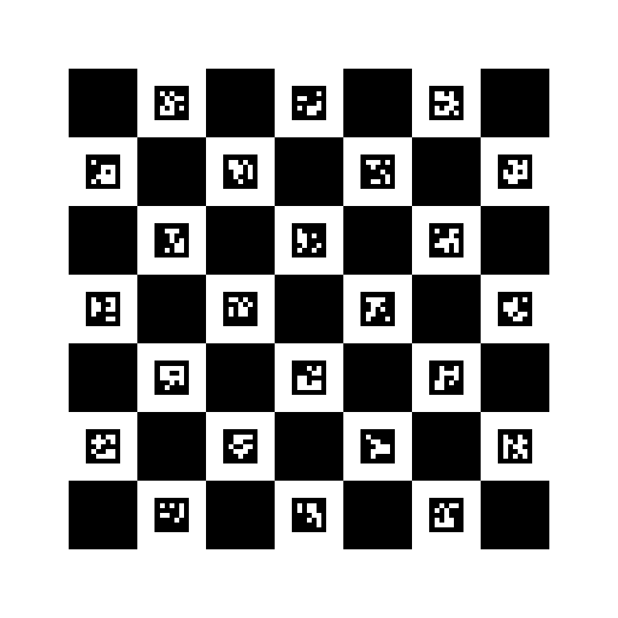
Example of a ChArUco calibration target
2. Cameras configuration
- Optical settings: the depth of field must be sufficient to ensure that the part remains in focus throughout the test
- Positioning: fix the relative positions of the cameras firmly in place. No relative changes should be made after the calibration target images have been taken, unless a new calibration is performed.
3. Positioning and framing the calibration target
- The calibration target should occupy at least 50% of the image, and its patterns should be correctly resolved.
- Ideally, place the calibration target where the part to be analyzed will be, at the position the area of interest will occupy during testing.
- If depth of field is limited or the part is bulky, it is preferable to temporarily remove the part to position the calibration target instead, or to move the whole camera system.
4. Checking image quality
- Always check images for sharpness, overexposure and reflections.
- Ensure that at least 90% of the calibration target is visible in the image for each acquisition, to guarantee reliable detection of markers and corners.
5. Taking images in different orientations
- Position the calibration target in the center of the field of view of both cameras.
- Capture images with various calibration target orientations:
- Zero rotation (calibration target plane parallel to image plane)
- Rotations of ±20° around the vertical axis
- Rotations of ±20° around the horizontal axis
6. Complete field-of-view coverage
- Repeat this operation in all four corners of the field of view to scan the volume space covered by the cameras and ensure accurate calibration over the entire test area.
- This procedure guarantees both the quality of the images required for processing and the reliability of the calibration parameters estimated by EikoTwin DIC.
For a more in-depth look at the subject, here’s our video on good practice when taking calibration target images:
What if synchronization isn’t possible?
In certain configurations where equipment or test constraints do not allow cameras to be synchronized, the hybrid calibration procedure remains an effective alternative (right-hand column in the first figure of this article).
👉 Find out more about this method in our dedicated article here.
Two workflows available after calibration
This new calibration allows you to choose between two workflows in EikoTwin DIC:
🔷 1. Automatic meshing
This workflow allows you to define a mesh directly on the images and perform 2D or 3D displacement measurements, without a finite element model.
➡️ No mesh alignment required, very fast process and usable results in less than 3 minutes.
Limitation: it does not allow test-simulation comparisons, since no correspondence is established with a finite element model.
🔷 2. Measurement on a finite element mesh
Complete workflow designed for cases where a test-simulation comparison is required or when you want to work directly in the part’s 3D reference frame.
It includes :
- Mesh alignment, to reposition and reorient cameras in the 3D frame via known points on the part in the mesh.
- Final calibration, which refines the projection matrices and updates the shape of the finite element model to take account of any deviations detected.
Conclusion
This new image-synchronized calibration method in EikoTwin DIC enhances the accuracy and robustness of measurement campaigns, and simplifies their implementation in configurations where synchronization is possible.
It paves the way for two distinct workflows:
- Automatic meshing, ultra-fast to implement for measurement-only cases.
- EikoTwin’s typical workflow with finite element mesh alignment, indispensable for in-depth analysis or simulation recalibration, with the possibility of more repeatable and robust calibration.
📖 This article is part of our Complete guide to digital image correlation.
98-100 AVENUE ARISTIDE BRIAND
92120 MONTROUGE
FRANCE