Hybrid calibration: a robust alternative to self-calibration
- By Pierre Baudoin, R&D engineer at EikoSim
Introduction
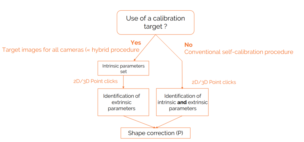
This article is written as a complement to the article on good calibration practices recently published on our website. In general, it is very often possible to calibrate the camera system in EikoTwin DIC thanks to the knowledge of the geometry of the part, and of the correspondence between points of the model and images of the structure at rest. In this case, the intrinsic and extrinsic parameters [1] of each of the cameras are initialized simultaneously during pre-calibration. However, in some cases, in particular when the geometry of the imaged part is very close to that of a plane, it can nevertheless be important to separate the initialization of the intrinsic and extrinsic camera parameters. In this case, we use “hybrid” calibration. The intrinsic parameters of each camera are obtained separately from images of calibration targets. In a second step, the extrinsic parameters are determined using the images of the component itself. Both procedures are summarized in Figure 1. To find out which procedure is the most adapted to your application, please read our dedicated article ; for now, let’s focus on hybrid calibration.
[1] As a reminder, the extrinsic parameters of a camera define the position and orientation of the camera in the global reference frame. The intrinsic parameters characterize the camera sensor/lens system (focal length, sensor size, optical center, skew).

In the first part, we will present the calibration targets used for the first step of hybrid calibration. In the second part of the article, we will describe the procedure to be followed when taking calibration target images to guarantee a good identification of intrinsic parameters.
ChArUco calibration targets
EikoSim has chosen to use “ChArUco” calibration targets to perform this hybrid calibration (Figure 2). Contrary to conventional checkerboard targets (chessboard type), each square can be detected and identified independently thanks to its unique ArUco marker. The advantage of these targets is that image processing is possible even when the checkerboard is not fully visible on the image. We use the OpenCV library to process calibration targets images.

We have defined a series of criteria to ensure that the calibration images acquired by the user will allow a correct determination of the intrinsic parameters :
- Number of images: we recommend 20 images per camera. These images can be acquired asynchronously between cameras, as the intrinsic parameters are determined independently for each camera. However, make sure that the target appear clearly in the images, as the corner detection algorithm may fail for blurry images.
- Calibration target size in the image: Ideally, the test pattern should occupy at least 50% of the image size, in all cameras. We recommend you scan the entire measurement volume as described in section 3.2.2.4 of the iDICs guide.
- Calibration target orientations: variations of 20° along the two axes of the image plane are sufficient to determine the intrinsic parameters accurately.
The software will check that these criteria are respected when processing the calibration target images.
Processing calibration target images with EikoTwin DIC 1.2
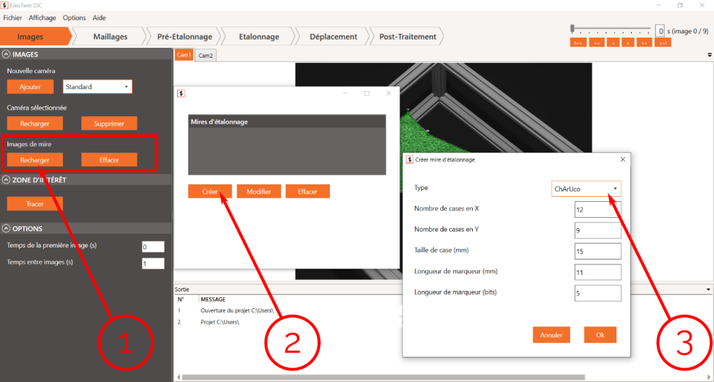
We import calibration target images into the software just after loaiding the test images in the “Images” tab of the EikoTwin DIC timeline. Beforehand, the user must first fill in a short description regarding the imaged calibration target (Figure 3). A ChAruCo test pattern is entirely defined by six parameters: number of cases along horizontal and vertical axes, case width (in mm), marker width (in mm), and the number of bits used to encode each marker.

This data is usually displayed directly on the calibration target (see Figure 2). Once the calibration target has been defined, the user can load a folder of target images for each camera. Once these images have been loaded, the software will analyze the test pattern images to determine if they meet the criteria described in the previous paragraph. If these criteria are met, the matrix of intrinsic parameters K returned by the algorithm will be used for the remainder of calibration,at which point only extrinsic parameters will be determined and updated.
The rest of post-processing in EikoTwin DIC 1.2 (shape and displacement measurement) is unchanged from previous versions of EikoTwin DIC. You are all set for your first post-processing with hybrid calibration!
