Thermomechanics on CFRP composite: tracking both crack and temperature with a single setup
When a crack propagates through a CFRP laminate, two phenomena unfold at the same time: the displacement field — the one conventional DIC measures very well — and the thermal heating at the crack tip, the signature of energy dissipation. Measuring them separately, across different test campaigns, is not only expensive — above all, it means missing half the physics.
The case presented here shows how EikoTwin and its thermal plugin make it possible to combine stereo DIC and an infrared camera on the same specimen, at the same instant — and to obtain three pieces of information where only two were expected.
The context: fracture toughness on CFRP
The study focuses on the fracture toughness of CFRP composites (carbon fibre/epoxy), a critical parameter for aerospace and space structures. The chosen geometry is the CT (Compact Tension) specimen, a standard in fracture mechanics: an initial notch forces the crack to propagate in a controlled direction during loading.
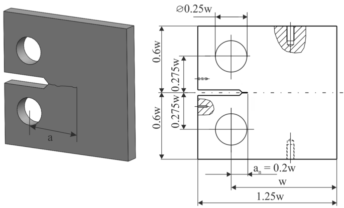
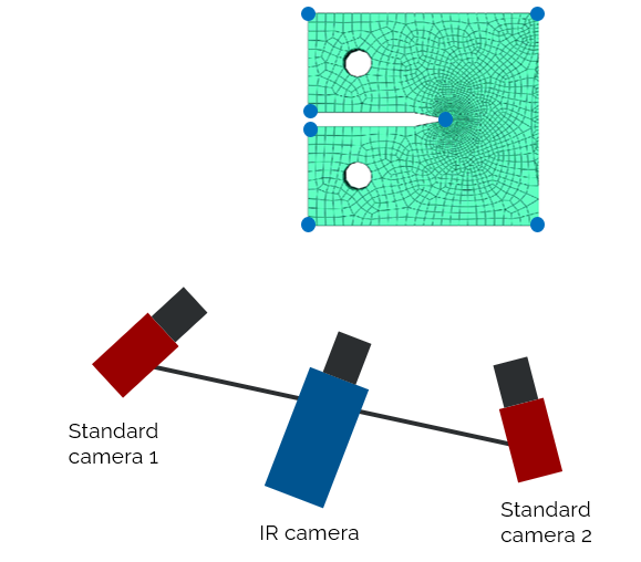
To compute K_Ic or the J-integral, you need accurate displacement fields around the crack tip. But to understand the dissipation mechanisms within the composite — delamination, inter-ply friction, local plasticity — you also need the temperature. The experimental setup includes:
- 2 standard cameras (stereo DIC system)
- 1 infrared camera
- Force and temperature sensors for synchronisation data
The result: 3 sets of images at different acquisition rates, to be reconciled within a common reference frame.
The technical challenge: 3 cameras, 3 reference frames, 1 physical truth
This is where conventional DIC hits its limits. Three cameras at different angles, with different frame rates and resolutions — calibrating all of it together into a single reference frame is a non-trivial problem.
EikoTwin solves this by using the finite element mesh as a common reference frame. The specimen geometry — known and modelled — serves as an anchor to calibrate the 3-camera system simultaneously. The mesh is not a floating measurement grid: it is a 3D object anchored in physical space, visible to every camera, and allowing all of them to speak the same language.
The key: Lagrangian temperature measurement
Once calibration is done, the thermal plugin computes the displacement U at every mesh node and at every instant. The IR camera, on the other hand, sees the deformed surface — it measures temperature at the current geometric point, not at the original material point. If the crack advances and the surface moves, the IR camera “loses track of” the material point.
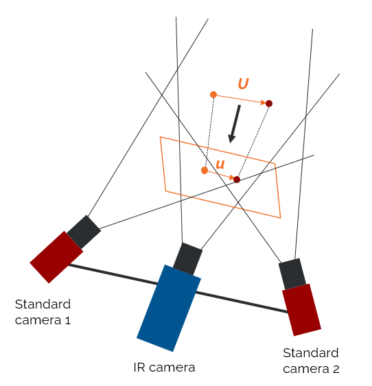
IR reprojection coupled with DIC corrects this: using the computed displacement field, you trace back to the temperature of the original physical point — this is measurement in the Lagrangian description. In practice, it avoids the artefacts that appear when you naively correlate an IR image with a DIC field without accounting for the motion between the two.

The results: two fields, plus a bonus
On the images obtained at the end of the test, the vertical displacement (conventional high-resolution DIC field) and the temperature (synchronised Lagrangian reprojection) are visualised side by side. Both fields clearly show how the crack-tip zone evolves throughout propagation.

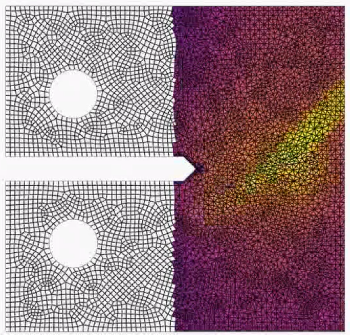
The unexpected bonus: the residual traces the crack
In DIC, the residual is the leftover error after registration — the difference between the reference image and the registered deformed image. In an intact region, this residual is low and uniform. In a region of discontinuity — a crack, for instance — registration cannot converge perfectly: the residual spikes locally.
The result: the DIC residual draws out the crack path — with no extra sensor, no manual thresholding, no edge-detection algorithm. It is information that emerges naturally from the DIC computation, and that EikoTwin makes directly visible in the interface.

What this changes for engineers
This case illustrates a central idea in the EikoTwin philosophy: information density per test. Running a test campaign is expensive — in machine time, specimens, and engineer-days. If you can extract twice as much information from the same setup, you cut the marginal cost of each measurement accordingly.
In this case, the outcome from a single setup:
- A displacement field usable for toughness computation (K_Ic, J-integral)
- A Lagrangian temperature field for energy and dissipation analysis
- A crack-propagation indicator via the DIC residual
- All of it projected directly onto the FE mesh — ready for test/simulation comparison
EikoTwin’s thermal plugin does not simply “add” an IR camera alongside DIC: it integrates it into the same measurement workflow, with the same reference frame, so the data are usable together straight out of the test.
Interested in a similar case for your application?
Write to us at or request a demo.
Acknowledgements: thanks to J. Naciri for the experimental data used in this article.
📖 This article is part of our Complete guide to digital image correlation.
98-100 AVENUE ARISTIDE BRIAND
92120 MONTROUGE
FRANCE