Forming and DIC: measurement of large deformations
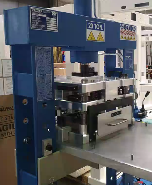
Experimental validation of forming processes, such as crimping, requires accurate characterization of local deformation fields, which can be achieved using DIC. A recent measurement campaign was conducted on an industrial part with severe geometric constraints, with an analysis area located on a section approximately 2 mm thick.
Beyond the small size of the area of interest, the bulkiness of the test bench and the presence of tools prevented the acquisition of intermediate images during the loading process. The analysis was therefore limited to comparing two discrete states: the initial state before loading and the final state after crimping. This temporal discontinuity, combined with significant plastic deformation and deterioration of the surface texture, renders standard image correlation algorithms ineffective, as they require incremental tracking to converge.
This article details the methodology implemented to address this issue. It is based on adapting the DIC system and using numerical simulation results to initialize the displacement calculation during forming, thereby enabling the kinematics of the part to be recovered despite the absence of intermediate images.
The experimental challenge: Macro-DIC and space constraints
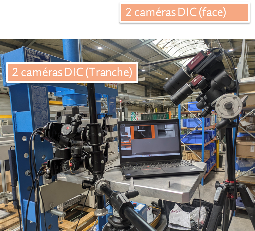
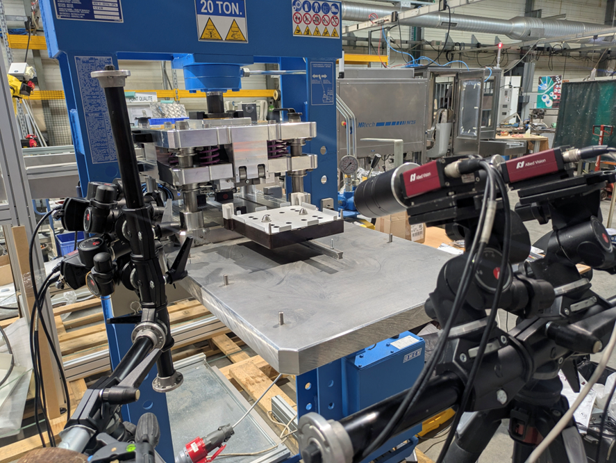
To meet the study’s objectives, the instrumentation was divided into two separate stereo systems, each addressing a specific area of the room with its own optical and geometric constraints.
Slice observation during forming: Macro-DIC and virtual pre-study
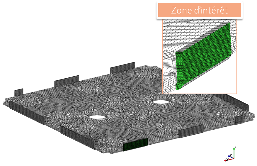
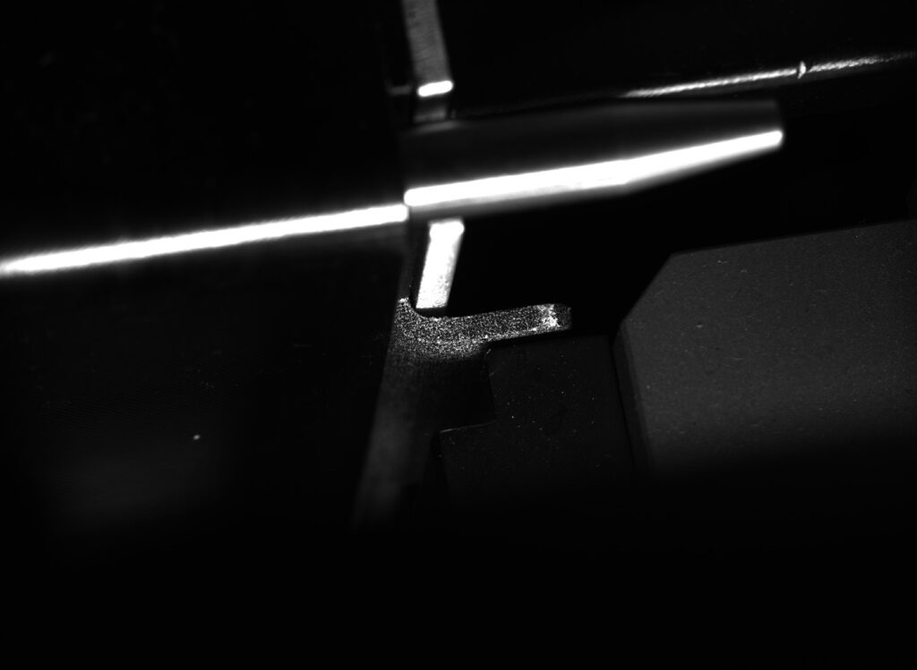
The first area of interest was located on the edge of the coin, a surface no more than 2 mm thick. To capture the deformation gradients at this scale, standard lenses did not provide sufficient spatial resolution. We therefore equipped the first pair of cameras with extension rings, thereby reducing the minimum focusing distance to achieve a macroscopic magnification ratio.
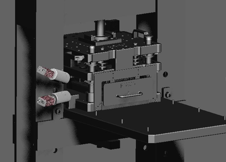
The integration of this system was hampered by the bulkiness of the test bench, where the frame drastically limits the available viewing angles. In order to ensure visibility of the area without interfering with the equipment, the positioning of the cameras was determined in advance by a virtual layout study carried out with EikoTwin Virtual. This simulation made it possible to validate the only viable optical window even before installation on site.

Observation of the face: the constraint of masking
The second pair of cameras was aimed at the side of the room. Continuous temporal tracking proved impossible in this area: the machine’s kinematics meant that the crimping tool completely obstructed the DIC’s field of view during the forming operation.
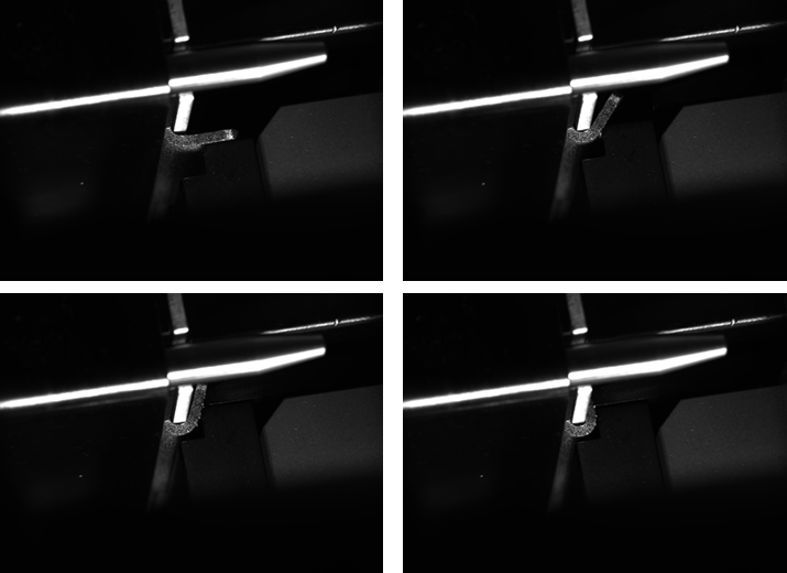
The acquisition strategy was therefore limited to capturing two static states: a reference image taken before loading, and a final image taken after removing the tool and opening the bench. Between these two shots, the part underwent complete crimping, characterized by a 90° bend and significant plastic deformation. The absence of intermediate images to track this radical transformation is the major difficulty in the analysis, rendering a conventional correlation approach ineffective.

Bridging the gap of large deformations through simulation
The two-stage acquisition on the face of the coin (initial state/final state) poses a fundamental problem for digital image correlation (DIC) analysis. Traditionally, DIC algorithms require a series of intermediate images to track the movement of the texture step by step. Here, the sudden transformation of the part—from a flat geometry to a 90° bend—causes significant displacement and local degradation of the speckles (appearance of cracks), which prevent any standard convergence.
Initialization by finite element simulation
To circumvent this break in temporal continuity, we implemented an initialization method based on numerical simulation. The EikoTwin DIC software, which uses the simulation mesh as a measurement medium, allows the theoretical displacement field predicted by finite element analysis (FEA) to be imported.
In concrete terms, the software uses numerical prediction to “pre-deform” the measurement mesh and project it onto the image of the final state. Instead of blindly searching for pattern matches between two radically different states, the algorithm starts its calculation from the position estimated by the simulation.
Model convergence and correction
This approach makes it possible to transform a large displacement search problem into a local optimization problem. The role of the DIC is no longer to find the entire deformation path, but to correct the discrepancy between the numerical prediction and the observed reality. This method ensured the convergence of the calculation despite the total absence of images during the crimping phase and the deterioration of the surface texture. It thus provides direct access to the test-calculation comparison, precisely quantifying where the simulation deviates from the actual geometry of the post-crimping part.
From theoretical meshing to reality in the field: detecting geometric deviations
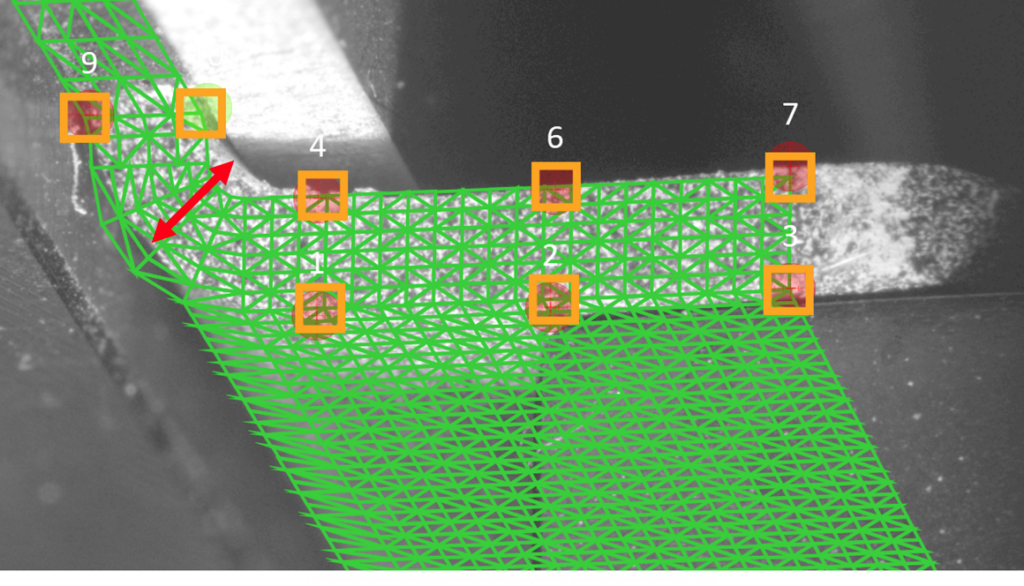
Once the mesh had been reprojected onto the images obtained through camera calibration, analysis of the results enabled a direct comparison between the geometry of the finite element model and the physical reality of the part. The use of the simulation mesh as a measurement aid offers a decisive advantage here: immediate visualization of topological differences.
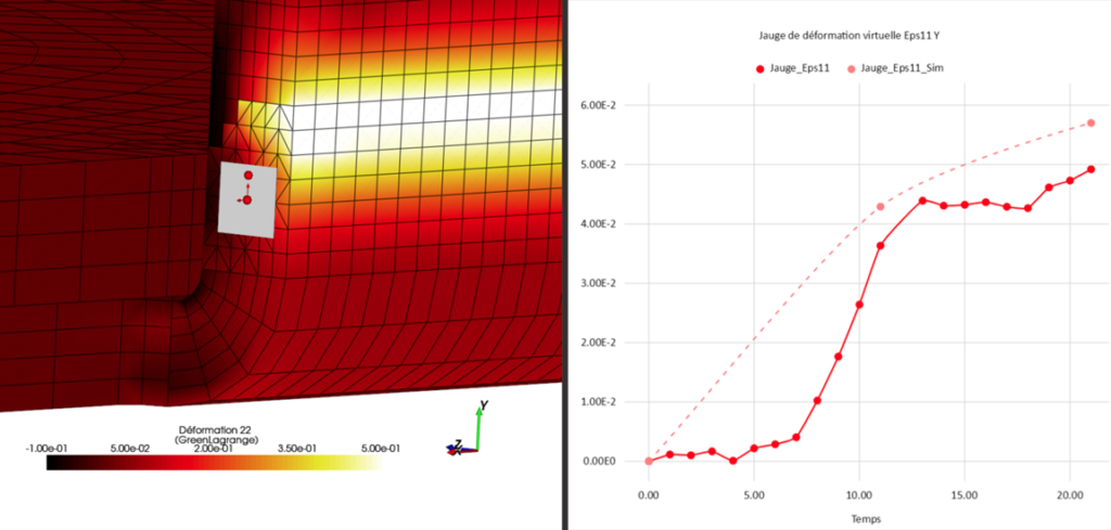
Superimposing the deformed mesh on the test images revealed a significant discrepancy. While the simulation model is based on perfect theoretical CAD geometry, the actual part exhibits variations inherent to the manufacturing process. The analysis revealed that the curvature of the modeled slice did not exactly match the actual curvature obtained after crimping (see below).
Impact on analysis
This geometric discrepancy is particularly pronounced in the bending zone, where there is also a difference in the thickness of the edge in the curvature compared to the numerical prediction. This difference in shape largely explains the discrepancy observed between the deformation values measured by image correlation and those obtained from the calculation.
This finding is crucial for engineers: it shows that the discrepancy between the test and the calculation does not necessarily stem from an error in boundary conditions or behavior laws, but from a fundamental difference in geometry between the part “as designed” and the part “as manufactured.” The method thus makes it possible to trace the source of the error in order to refine future simulation models.

Conclusion
This study confirms that experimental analysis of forming using stereo image correlation (DIC) remains relevant and feasible even in the heart of bulky equipment and on very small geometries. The success of this measurement on a crimping operation is based on two pillars: meticulous preparation upstream (virtual validation of camera placement, macroscopic optics) and strong synergy between testing and calculation.
Initialization using numerical simulation proved to be the cornerstone of the analysis. It made it possible to overcome the loss of temporal tracking caused by tooling obstruction and to converge the calculation despite the severity of plastic deformation and surface degradation.
Ultimately, this methodology offers much more than simple mechanical validation: it allows the digital model to be directly compared with the reality of the manufacturing process, highlighting actual geometric deviations (thicknesses, radii of curvature) that are often ignored by the perfect theoretical model. A hybrid analysis-DIC approach is essential for ensuring the reliability of industrial forming simulations.
98-100 AVENUE ARISTIDE BRIAND
92120 MONTROUGE
FRANCE