Digital Image Correlation – The basics
By Florent Mathieu, CEO of EikoSim
What is digital image correlation?
The Digital Image Correlation (DIC) technique is a non-contact, full-field measurement approach that enables the assessment of the deformation and motion of objects.
This is achieved by comparing digital images of the object before and after deformation.
DIC measurement is a technique used to track surface patterns on an object.
It involves capturing images before and after deformation to gather data on displacement and strain.
What is displacement in image correlation?
“Displacement” is the movement of a point or area on an object’s surface before and after deformation. In the context of DIC, displacement is measured by tracking markers or patterns on the object’s surface.
By comparing the positions of these markers in images captured before and after the deformation, the software can calculate the displacements at various points on the object.
Typically, displacement is represented as a vector quantity, which conveys both the magnitude and direction of the movement.
What is deformation in image correlation?
Deformation refers to the alteration in size or shape of an object that occurs due to external forces or applied loads.
This change in geometry during the deformation process is characterized by DIC, which allows for the measurement and analysis of deformation by quantifying the strain fields.
Strain, derived from displacement data, is a measure of the object’s relative change in shape or size.
Digital image correlation process and output data
The process includes image acquisition, preprocessing, identifying patterns or markers, analyzing deformation, and post-processing and visualization.
To measure how an object changes shape and moves, a camera or group of cameras take high-quality images before and after the change occurs.
These images go through different processing techniques to improve their quality and reduce any unwanted effects that could interfere with tracking.
Then, the digital image correlation software identifies and tracks specific markers on the object’s surface using correlation-based methods or feature detection algorithms.
Comparing the positions of these markers helps the software calculate the displacement and strain fields, which reveal important information about localized strain distributions.
The digital image correlation software can then extract relevant data and present it visually by using techniques like contour plots or animations.
DIC system and software applications
There are many different areas where DIC software can be applied, such as material testing, structural engineering, biomechanics, and geotechnical engineering.
Digital image correlation is especially helpful for studying mechanical properties and complicated deformations and getting detailed strain information.
DIC is a non-invasive method (or non-contact optical technique) that can measure an entire field, so it’s a great resource for grasping how objects react to different types of loads.
Digital image correlation in engineering
DIC is commonly employed in experimental mechanics and materials science to obtain accurate and reliable measurement data for mechanical properties and beyond.
In the mechanical engineering field, digital image correlation has been widely used to monitor and process test data in both research and industrial contexts, for applications ranging from common material testing to characterization of massive and complex components (part of an airplane or a helicopter, roadway bridges, nuclear power-plant structures).
The method is very versatile and can be applied indifferently to structures of any shape, size, or material, as long as they can be observed by cameras. It is also a contactless and non-destructive technique.
What are digital image correlation algorithms?
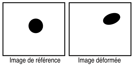
Digital image correlation algorithms are based on the tracking of information across a set of images, from a ‘reference image’ to pictures taken later in the test, often called ‘deformed images.
This set of images constitutes a movie from which the displacement measurement will be derived.
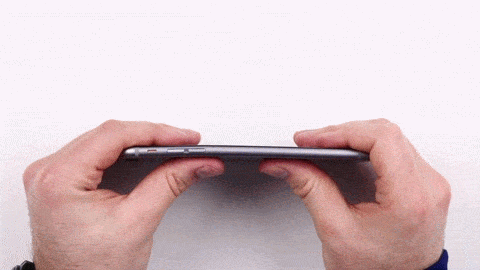
source : UNBOX THERAPY/YOUTUBE
In the example illustrated above, our eyes perceive a deformation because the human brain remembers the initial configuration (no load applied to the phone) when it processes pictures of the deformed phone.
Digital image correlation algorithms process digital images taken from cameras in a similar way:
Just like the human eye, a digital image correlation algorithm must be able to determine the displacement (i.e., rigid body motion that is a combination of rotation and translation) and deformation of a pattern across several images:
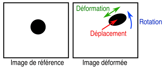
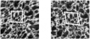
Digital image correlation can be summarized as the tracking of a set of points (or markers) across the observed surface: the motion of a part surface is known when the individual motions of all markers on this surface have been determined.
This implies that the measured part needs to be textured before its motion can be recorded. For instance, if the surface texture is only constituted of a black dot in the middle of a white area (as illustrated above), displacements cannot be evaluated inside the white area surrounding the black dot.
Conversely, ‘periodic’ texture patterns should be avoided because it will become difficult for the digital image correlation software to determine individual point locations unequivocally.
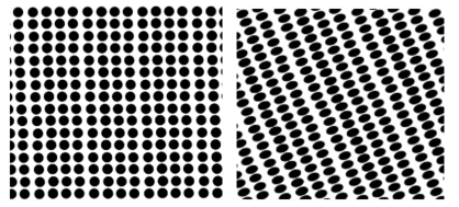
To remove this ambiguity on individual point locations for digital image correlation, a random texture that allows one to distinguish the vicinity of a given point from the surrounding areas.
For parts with sizes ranging from a centimeter up to a meter, paint speckle patterns are often directly sprayed on the sample surface. The resulting texture is made of randomly distributed speckles of 1mm in average diameter.
Every measurement point (in practice, every image ‘subset’) can then be distinguished from its surroundings.
Acceptable textures for DIC can be obtained from other methods, for imaging techniques ranging from Secondary Electron Microscopy (SEM) and X-Ray tomography up to observations of much larger structures.
Some materials are naturally textured (concrete, sand, or even metals at the microstructure scale) and do not require the application of an artificial texture to be characterized.
The measurement accuracy of digital image correlation can seem surprisingly high. It is due to sub-pixel grey level interpolation: if a black spot with a diameter of 1 pixel is translated across a uniform white background, the neighboring pixels will react to this displacement by taking a grey level value proportional to the surface of the dot overlapping this pixel.
Sub-pixel interpolation makes it possible to commonly measure displacement amplitudes smaller than 0.1 pixel, and even smaller than 0.01 pixel in favorable experimental conditions.
To achieve this precision, great care must be taken in providing constant and uniform lighting to the observed sample, and image acquisition must be carried out with high-quality lenses and cameras.
By design, classical digital image correlation approaches are well adapted to compute point cloud displacement data, by repeating the previous operation over several image subsets where displacement is sought.
From a design office perspective, this data format not ideal, because the experimental data needs to be compared to numerical simulations results (typically produced by FE software such as Abaqus or Ansys) which will be expressed on the nodes and elements of a finite element mesh.
For mechanical engineers, a better solution to make comparison between experimental and numerical data is to use the simulation mesh as a basis for displacement measurement, instead of independent image subsets:
In this context, the choice of shape functions is paramount; not so much for the test engineer (whom this choice will not impact), but for the structural engineer that will need to compare the experimental data with the prediction of the simulation model.
In practice, projecting point cloud data to the FE space involves several problematic operations (change of coordinate system, 3D data interpolation) that can result in unwanted error and bias.
Taking the FE mesh as a basis for measurement from the very start greatly simplifies the processing of the experimental data for the structural engineer.
This is possible thanks to the use of a global method based on an assumption of continuity of displacement fields in the problem formulation.
For actual three-dimensional components, it is not possible to acquire comprehensive displacement data using a single camera, because a single camera can only determine displacements in the plane parallel to its sensor (2D measure). To measure 3D displacements, a multi-camera (2 or more) system is required:
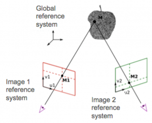
The previous grid points can be illustrated in the above figure. In this configuration, a translation of the physical point M along the (M-M1) axis will not affect the position of M in the image acquired by camera 1, whereas camera 2 will be able to detect this displacement.
For complex sample geometries, this basic concept can be extended to use as many cameras as necessary to measure displacement and strain across all desired component surfaces.
3D-DIC data that was acquired throughout the test can then be matched with information gathered from other sensors (force, punctual displacement or strain) to validate and enrich the numerical modeling.
In some cases, the DIC technique or digital image correlation process can even be automated to estimate constitutive parameters from digital image correlation measurements.
📖 This article is part of our Complete guide to digital image correlation.
98-100 AVENUE ARISTIDE BRIAND
92120 MONTROUGE
FRANCE