Desing of a Thermomechanical Test Bench — Coupled DIC and Infrared Imaging
This article was written in collaboration with Thibaut Archer, researcher at ONERA.
Setting up thermomechanical tests in a controlled environment is a major challenge for validating numerical models in structural mechanics. Optimum design of the test rig is essential to ensure accurate acquisition of displacement and temperature fields, via DIC and IR measurements, particularly when the part under test is subjected to extreme temperatures. The integration of a thermal enclosure with carefully positioned portholes guarantees optimum capture of the mechanical and thermal fields.
This article presents a methodology for optimising ONERA’s Simba test bench using EikoTwin Virtual, a simulation tool for anticipating instrumental constraints. The study focuses on the orientation and position of the portholes to ensure optimum positioning of the cameras, maximising the common depth of field and the shared field of view between the visible and thermal sensors. The experiment was carried out on a specimen subjected first to intense laser heating to over 1000°C, then to progressive traction, with simultaneous acquisition of the displacement and temperature fields on several faces of the specimen.
The results show that prior simulation of the test bench enables significant optimisation of the experimental parameters, guaranteeing better-quality measurements and reducing uncertainties. The measurements will make it possible to identify the material’s threshold properties and help industrial partners in their design of parts.
Introduction
Thermomechanical testing is essential for studying the response of materials and structures to extreme conditions. The combined use of digital image correlation (DIC) and infrared (IR) thermography provides simultaneous access to displacement fields and temperature variations on the surface of a specimen. However, these techniques require specific observation conditions, which become complex when the test takes place in a thermal enclosure.
The Simba test bench had to be designed with these constraints in mind. The aim of the tests carried out on the test bench is to get close to an engine environment on a material scale in order to characterise and understand the damage mechanisms, particularly in the presence of thermal gradients.
The presence of this enclosure imposes constraints on the position and orientation of the optical sensors, requiring the integration of portholes for optimal measurement acquisition. These portholes must be sized and positioned to maximise the depth of field and ensure complete coverage of the areas of interest on the test specimen. In addition, the configuration of the cameras must be designed to capture different faces of the part under test simultaneously, particularly in the context of complex thermomechanical loading.
The use of EikoTwin Virtual enables the test environment to be modelled digitally and the position and orientation of the windows to be optimised beforehand. The aim of this study is to demonstrate that the preliminary simulation of the test bench makes it possible to anticipate and resolve the problems associated with the acquisition of measurements even before the physical implementation of the test, thereby reducing experimental iterations and improving the quality of the data obtained.
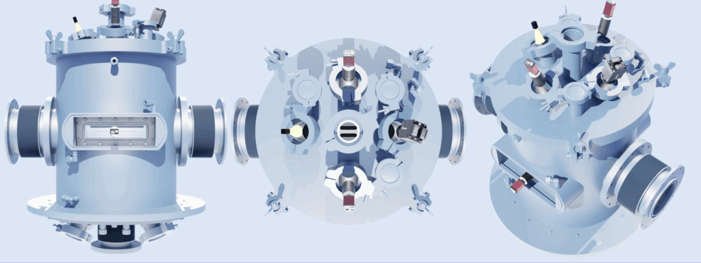
Design and simulation of the test bench and thermal enclosure
Optimisation of the test rig begins with numerical modelling of the thermal enclosure and camera positioning. The experimental configuration includes a laser heating system capable of reaching temperatures in excess of 1000°C, followed by mechanical tensile stress.
The main objective is to ensure optimum capture of the mechanical and thermal fields by strategically positioning the sensors. Five cameras are integrated into the system: two visible cameras are positioned to observe the top face of the specimen, providing optimum coverage of the displacement fields; one thermal camera is dedicated to observing the top face, ensuring that thermal variations in the heated zone are recorded; a second thermal camera is positioned under the specimen, providing a complementary view of the heat distribution and thermal response of the material; and an additional visible camera is aimed at the edge of the specimen to capture the displacement fields along the tensile axis.
The position and orientation of the portholes are defined to ensure a shared depth of field by the visible sensors, allowing the cameras to focus simultaneously on the entire surface of the specimen. The field of view is optimised by simulation.
The placement of the portholes is adjusted according to the angles of incidence of each sensor, in order to minimise reflections and maximise the quality of the data acquired. A study is being carried out to test several configurations of porthole size and orientation, ensuring optimum access to the areas of interest while maintaining a robust structure for the thermal enclosure.
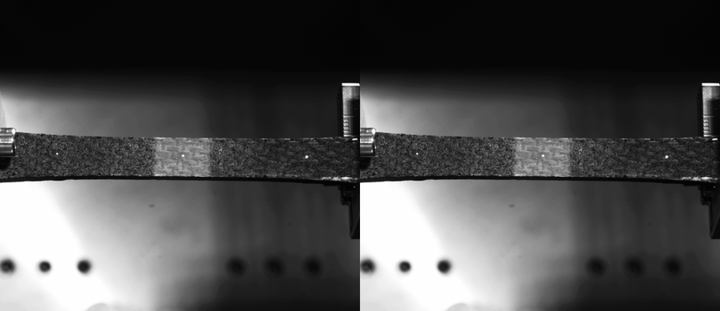
Carrying out the DIC+IR test and acquiring measurements
After numerical validation of the bench configuration, the thermal enclosure was manufactured and integrated into the experimental set-up. The specimen is initially subjected to intense laser heating, enabling temperatures above 1000°C to be reached in specific zones. Once the thermal distribution has stabilised, a progressive tensile load is applied to observe the evolution of the deformation fields under load.
The optical sensors are installed according to the configuration validated by simulation. The visible and thermal cameras are positioned so as to capture the mechanical and thermal fields simultaneously, with synchronous monitoring of the data from the different sensors.
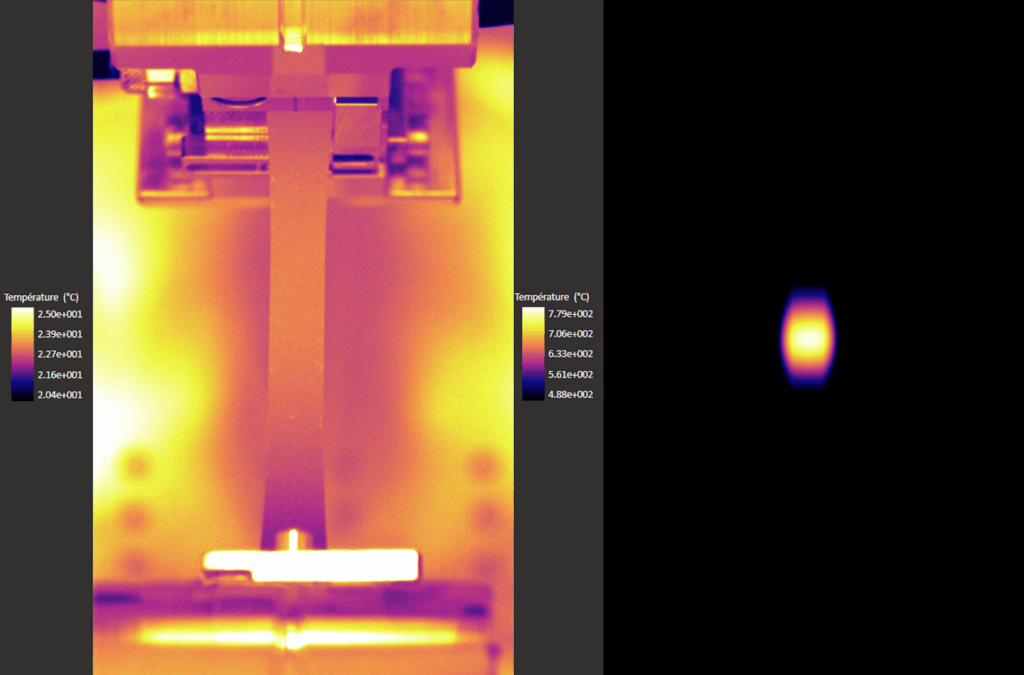
DIC images are processed to reconstruct displacement fields and identify stress concentration zones. Analysis of the thermal images highlights the propagation of heat within the specimen and its influence on the mechanical response of the material.
Above all, the combined use of DIC and IR images means that, thanks to the coupling plugin developed for EikoTwin DIC, deformation fields can be obtained directly as a function of the local temperature measured. This capability is the major advantage of the device: it provides simultaneous access to spatially and temporally correlated mechanical and thermal data on the part under test. This makes it possible to study precisely the evolution of deformation under complex thermomechanical stresses, and to validate material models that take thermo-dependent effects into account.
Discussion of the results
By optimising the test rig beforehand, we were able to guarantee data acquisition without any significant disturbance, with a shared depth of field between the DIC and IR cameras.
The approach, based on the prior simulation of the test bench, has made it possible to reduce the number of experimental iterations and optimise the use of data from the first series of tests. This methodology ensures better reproducibility of the tests and increased reliability of the measurements obtained.
Conclusion and outlook
The study demonstrated that the use of EikoTwin Virtual for the design of thermomechanical test benches enables efficient optimisation of experimental parameters, guaranteeing better quality measurements and reducing uncertainties. The integration of optimally positioned portholes has enabled complete coverage of the areas of interest and synchronised acquisition of the DIC and IR-measured fields. The measurements will make it possible to identify the material’s threshold properties and help industrial partners to design parts.
98-100 AVENUE ARISTIDE BRIAND
92120 MONTROUGE
FRANCE