Toward quantitative image analysis of Bird strike tests
- By Florent Mathieu, CEO of EikoSim
Redactors : N. Cordero, F. Fremy, M.Beneck for Saint-Gobain, F. Mathieu for EikoSim
Aircraft radomes produced by Saint-Gobain are made of composite materials. In addition to the usual design requirements that these structures must comply with (lightness, aerodynamic shape, impact resistance), they need to be RF transparent so that the systems they shelter may function. This last point drastically limits the number of applicable materials and imposes a specific design on the composite material.
Optimizing radome structure and assembly design is paramount to ensure satisfactory mechanical performances despite these limitations. Moreover, the fast evolution of embedded communication systems requires frequent design updates based on reliable and efficient analysis tools. Material characterization tests are of utmost importance and need to be performed at realistic loading speeds for the intended application.
The assembly with the plane fuselage also needs to be characterized and validated trough mechanical testing. The goal of this work is to optimize this critical area in order to meet the qualifications criteria and ensure optimal in-flight structure performance.
In order to study impact resistance, impact tests are usually carried out at speeds close to plane landing or takeoff (approx. 150m/s): these bird strike tests are well established in the industry, whether they are conducted with birds or gelatinous approximations.
As the impact speed is quite high, many testing centers have acquired high-speed cameras (acquisition speed ranging from 100 up to a few thousand frames per second) that make great diagnostic tools to establish structure damage and fracture modes.
These images are used as qualitative complementary information in conjunction with more conventional sensors (laser, strain gauges) on which St Gobain engineers rely for their quantitative analyses.
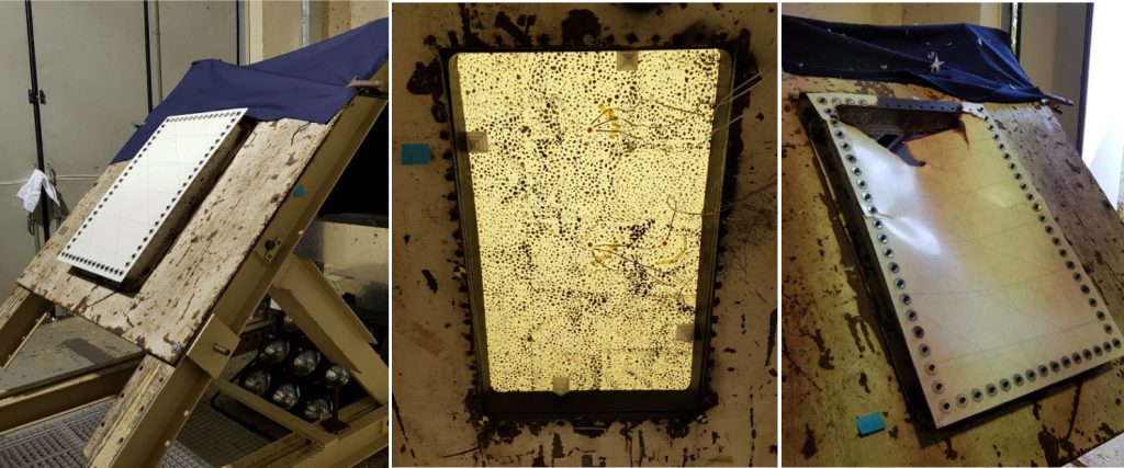
Figure 1 – Test setup of a bird strike test on a composite material (approximate size: 80 x 50cm)
The drawback of these conventional sensors is that they produce only local, scattered information, which can be hard to relate to numerical simulations.
If the sensor is slightly off position or if the impact does not occur exactly where it should have, the test result can vary in significant proportions.
Test instrumentation using 2-dimensional digital image correlation (DIC) is well established at St Gobain, so the opportunity to extend this approach to out-of-plane motion thanks to stereo DIC was a natural outcome of their previous work. Camera positioning was carried out specifically for a bird strike test, and the camera outputs were synchronized.
In the present case, the strike was performed on a glass/epoxy material in order to test the method as well as to determine the material response for this simple load path. To enable the instrumentation with DIC, a paint speckle pattern was deposited on the sample surface opposite the impact (see Fig.1).
For this application, stereo DIC is carried out directly with the EikoTwin DIC software on the FE mesh used in the simulation. This measurement enables the comparison of measured results directly to their numerical counterparts.
Using image information allows us to obtain a broader estimate of the structure deformation under strain, and even to cover a longer length of time than the usual sensors. Indeed, because of the energy generated during impact, large strain and damage occur in the sample, and the gauges wiring often get ripped off during testing.
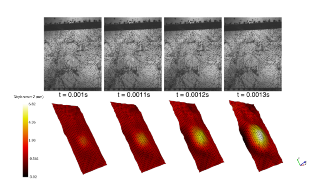
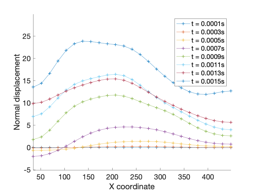
Post-processing these tests with DIC thus allows to understand how the structure behaves over time, and the influence of the damage mode on the mechanical resistance of the fixations (see Figs 2 and 3) around the component.
Fig. 3 shows that the loading is dissymmetric, especially near the left of the image, where strain mostly propagates during the first milliseconds. Such a behavior could not have been evidenced using conventional sensors, and by itself this result leads to a better understanding of actual component behavior for researchers.

Figure 2 – Images of the structure taken between t=0.001s et t=0.0013s, and displacement profiles measured at these instants. Image processing provides a displacement profile that could hardly have been anticipated by direct observation.

Figure 3 – Displacement profiles over time along the horizontal central line, as measured by digital image correlation
The next step for this test is to run the test-simulation comparison with the digital twin in order to identify the constitutive parameters of the composite material.
The global outlook provided by DIC gives us the opportunity to validate the boundary conditions, which are a critical point in theses simulations.
The fact that the measurement was carried out directly on the FE mesh will allow to make the comparison directly.
The final objective of this fundamental step will be to conduct a robust identification of the constitutive law for testing conditions close to the industrial application for which the simulations will be performed.
You can also find this article in the April issue of the Essais & Simulations magazine (n°137) !

