Digital Image Correlation, how to choose your acquisition hardware?
We have already seen together the principles of digital image correlation and the contributions of such measures. Today we will see how to choose its acquisition hardware so that it is adapted to the different use cases encountered.
Image acquisition equipment means the cameras of course, but also the lenses, the lights, the mounting brackets and the hardware used to synchronize the images. It is possible to equip yourself in order to cover a variety of use cases.
The camera choice
First, before choosing a camera model, you need to determine the type of applications and the physical phenomenon you want to observe. Are your applications mainly quasi-static tests, fatigue tests, or impact tests?
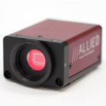
The speed of solicitation gives us information on the evolution rate of the measured kinematic quantity. The faster the workpiece deforms, the higher the camera’s acquisition frequency should be, to be able to measure the displacement evolution within that time frame. As part of a test where the impact speed is around 150 m/s, the use of “fast” cameras (frequency ranging from 100 to several thousand images per second) is necessary. There are a lot of cameras available on the market. However, for Digital Image Correlation, cameras equipped with a CCD sensor will be more suitable because it offers high dynamics and high sensitivity.
Is the observed phenomenon 3D or 2D? If the observed surface deforms in the three directions of the space, it will require a 3D measurement, and thus two or more cameras observing this area of measurement. If the surface is flat and deforms in its plane, then only one camera is enough and a 2D measurement will be obtained.
It can also be fairly simple to calculate the uncertainty of measurement that can be expected in a given situation. For example, let’s take a 2D case in which the observed area is 200×200 mm2 and the camera has a definition of 4 Mpx (2000×2000 pixels). Regardless of the camera, Digital Image Correlation generally allows for a measurement uncertainty of less than 0.1 pixel. This uncertainty will of course depend on the test conditions but also on the acquisition noise of the camera. By applying a simple rule of three, it is estimated in this case to be able to achieve a measurement uncertainty of the order of 0.01mm.
If we want to reduce the uncertainty, we can use a camera that has a larger resolution: If we increase the number of pixels for the same area observed, we decrease the “physical” size of the pixel, and thus the uncertainty decreases.
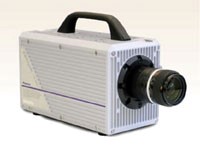
However, the larger the sensor size, the more information the camera will have to send to the PC for each image, and the acquisition frequency will decrease. Example: in the same range of quality, we can find cameras with a resolution of 12Mpx allowing an acquisition frequency of 10Hz, or a resolution of 0.4 Mpx and a frequency of 270Hz. These cameras have the same bandwidth but will not be used for the same applications.
The lenses choice
Is it necessary to observe the whole part or structure? Or should we focus on a restricted area? The choice of the lens will determine the width of the field of view. The parameters to be considered are the working distance, the size of the area to be observed and the physical size of the camera sensor. The ideal is to choose a lens with the largest focal length to guarantee the working distance and the area to be observed. Like this, one will also limit the optical distortions of the lens.
If the working distance is known, the focal length to be selected can be calculated directly with the following formula:

with h the sensor size in the horizontal direction, WD the working distance and horizontal FOV the desired size of the scene.
Let’s take for example the following case in which a beam of 2m wide at a working distance of 2.5 m is observed. The chosen camera has a sensor size of 22.5 mm, so it will be necessary to choose a lens of 25 mm [1].
The lights choice
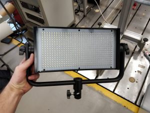
For lighting, it is necessary to have an uniform and constant light source in time to ensure optimal image processing. Indeed, as we have seen in the previous articles, the Digital Image Correlation measurement is based on the gray level conservation between two time steps for which images are captured. Therefore, it is preferable to have a light source specifically illuminating the area to be observed. Power-adjustable led panels are classically used. It should be remembered that the higher the camera acquisition frequency is, the lower the exposure time and therefore the more powerful the light source should be.
The mounting brackets choice
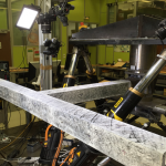
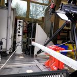
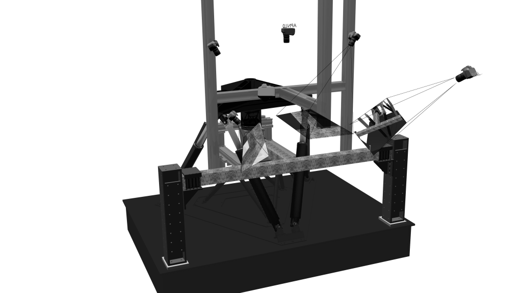
The choice of mounting brackets is also important because it is essential that the cameras remain stable during the test in order to guarantee the quality of the Digital Image Correlation measurement. For a standard use of Digital Image Correlation on test specimens (instrumentation on a tensile test for example), it is generally advisable to use a tripod and to fix two cameras on a bar connected to this tripod (opposite). This gives a rigid set to limit the needed space and relative movements between cameras.
However, in the case of complex structural tests, access to the observed areas can be tricky given the test environment. The cameras will then have to be arranged independently of each other either on separate tripods or on a chassis specifically designed for the test machine, as in the test on the concrete beam opposite.
