Understanding and controlling the sources of discrepancy between tests and simulations
- By Renaud Gras, Co founder – CTO of EikoSim
Adjustment and validation of simulations
Simulation is crucial in the development, approval, and certification of industrial products and services. It is the foundation for strategic business decisions and projects, making experimental testing even more significant. Testing and output of measured results used to be a mere requirement for compliance demonstration, but now it serves as a benchmark for validating the accuracy of numerical simulations[1, 2].
Thus, learning, adjusting, and validating numerical simulations to be as predictive as possible and closely reflect reality is becoming crucial. To adapt, update and predict the mechanical behavior of s component or structure, use data, and develop insights from tests designed to improve simulation performance.
Limitations of the traditional approach
Traditionally, when simple material testing is carried out, the applied forces are well controlled, and conventional instrumentation, such as a strain gauge, equip the test piece. These standardised tests ensure a homogeneous deformation in the sample in order to identify a model parameter [3]. In this context, the determination of complex models requires a lot of tests. Moreover, this strategy cannot be applied to tests on structures for which the geometry and the constitutive model are more complex.
Simulation data can provide the team with more information than physical sensors, but sensors only capture data in the form of one specific area, leading the team to focus on potential missing information.
These sensors do not cover the entire part, and their measurements are not expressed in the reference frame of the simulation, which makes the comparison between the test and calculation more difficult. Furthermore, in case of disagreement between experimental and simulated data, it is often extremely difficult to identify the causes of this difference because the measurements are localized. It is, therefore, possible that the actual critical area was not instrumented. Does this gap come from the mechanical behaviour, the boundary conditions, or the simplifying assumptions made in the model?
To answer these questions, further simulations or even additional tests on prototypes are needed, which means a cost and a time overrun.

The 3D model to ensure the data continuity
To ensure numerical continuity, the systematic use of the 3D model from CAD to validate the simulation is proposed. The model is used:
- to define test specifications,
- to design and carry out virtual tests implementing all sensors attached to the prototype in its testing environment,
- to perform measurements during the actual test,
- and finally, to adjust and validate the numerical simulation.
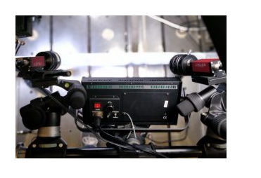
To perform the last two steps, the test subject can be instrumented with imaging devices, and the measurement during the actual test can be measured by Digital Image Correlation [4] using the 3D model as a reference.

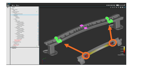
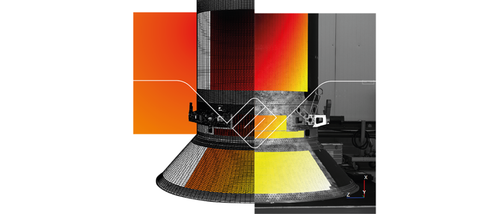
Thus, the measurement is performed directly in the reference frame of the numerical simulation, and the measured results are expressed on the finite element mesh. The comparison between test data and simulation data is, therefore, immediate.
Additionally, the areas where the difference is significant can be identified in case of disagreement. Further, the measurement data is large thanks to acquiring a displacement field. These measurements, expressed on the finite element mesh, enable automated model adjustment using the finite element model updating (FEMU) method. This identification can be weighted by the measurement uncertainty to obtain the new model parameters and their uncertainties compared to the data used as a reference.
The advent of image-based measurement techniques enables significant measured data enrichment and the simultaneous identification of several model parameters with only one test, thanks to the nature of the measured heterogeneous field [5].
The 3D model becomes the basis for creating a digital twin around the world in which data is gathered.

Towards an accurate estimate of the various sources of deviation
For finite elements simulation programs, three common sources of errors are often encountered: discretisation errors and errors, model errors, and some form of numerical errors. Checking for discretization errors and some form of numerical errors is a common process in numerical studies, and the validation process is mature enough to keep them under control [6].
Thus, only model errors will be considered here. These are the error mainly due:
- to the improper specification of the boundary conditions, which differ from what has been done in the actual test conditions,
- to the fact that the constitutive parameters of the model do not reproduce the actual material behavior accurately.
The integration of test data on the finite element mesh used for learning and training the simulation enables the systematic adjustment of the performance of this simulation using an identification method. The article recently published by S.Roux and F.Hild provides an optimal identification correction method based on the choice of an appropriate standard taking measurement uncertainties into account [7].
These sources of measurement error and uncertainties by Digital Image Correlation (DIC) are related, for example, to the image noise and the camera system calibration error. It is also relevant to consider, for example, the uncertainties in boundary conditions due to the gaps in assemblies, the misalignment of the cylinders or the distribution of the applied boundary conditions.
When adjusting the simulation, it is essential to examine and separate constitutive model errors from errors due to boundary conditions differences between what has been chosen in the simulation and what has been applied during the test. To be fully independent of the errors due to applied forces, FE mesh-based digital image correlation is the suitable tool, because then boundary conditions can be measured and directly introduced into the numerical simulation as was done in the case of a train chassis in collaboration with ALSTOM and CETIM.

Assuming the camera system calibration error analysis has been done correctly, the other error analysis-associated uncertainties can be neglected. Then only measurement uncertainties due to sensor acquisition noise remain. Image correlation noise can impact measurements, affecting identified parameters. Understanding this can improve parameter accuracy.
We account for measurement uncertainties and enforce boundary conditions in the simulation process for accurate results. Any discrepancies with the actual measurements are attributed to the model’s constitutive parameters.
Conclusion
The 3D model is used as a digital twin throughout the design cycle, and the team can gather full-field experimental data. Therefore, it provides the team, whole firm, whole company, client organization, and whole team of employees with the following benefits:
- Ensures the continuity of the design digital chain,
- Aggregates simulation data and test data,
- Validates the numerical simulation and, in case of disagreement between experimental and simulated data, adjusts the implemented mechanical model.
Accurate numerical simulation suggestions for better-measured results:
For more accurate numerical simulations, consider boundary conditions and results from digital image correlation. This helps distinguish errors from testing and model errors. Also, estimate image acquisition noise to determine parameter uncertainty.

References
[1] https://www.nafems.org/professional_development/nafems_training/training/verification-validation-des-modeles-et-analyses/
[2] https://www.asme.org/products/codes-standards/v-v-101-2012-illustration-concepts-verification
[3] https://en.wikipedia.org/wiki/Tensile_testing
[4] Dubreuil, L., Dufour, JE., Quinsat, Y. et al. Exp Mech (2016) 56: 1231. https://doi.org/10.1007/s11340-016-0158-x
[5] Jan Neggers, Olivier Allix, François Hild, Stéphane Roux. Big Data in Experimental Mechanics and Model Order Reduction: Today’s Challenges and Tomorrow’s Opportunities. Archives of Computational Methods in Engineering, Springer Verlag, 2018, 25 (1), pp.143-164. https://dx.doi.org/10.1007/s11831-017-9234-3
[6] P. Ladevèze and D. Leguillon. Error estimate procedure in the finite element method and applications. SIAM J. Num. Analysis, 20(3) : 485 – 509, 1983.
[7] Stéphane Roux, François Hild. Optimal procedure for the identication of constitutive parameters from experimentally measured displacement fields. International Journal of Solids and Structures, Elsevier, In press, https://dx.doi.org/10.1016/j.ijsolstr.2018.11.008
