Local DIC or Global DIC: Which is the Best Method for Your Application?
Introduction
Digital Image Correlation (DIC) relies on two main algorithmic families: local DIC (or subset-based) and global DIC (or FE-based). Both approaches produce displacement and strain fields, but their internal workings, strengths, and limitations can be different.
First, it is important to note that in 90% of cases, the results of the two methods are identical, barred measurement errors. An article (currently being published) about the DIC challenge organised by the iDICs society highlights the significant similarities between the two methods, and there is often more variation (in displacement and deformation) between two implementations of the same method than between the two methods themselves.
That said, we thought this article could help to separate fact from fiction and understand the differences that may remain and the benefits of using one or the other depending on the circumstances.
Local DIC: the subset principle
How it works
Local DIC divides the image into small square regions called subsets (or correlation windows), typically 15 to 50 pixels wide. For each subset, the algorithm searches for the position in the deformed image that maximises a correlation criterion – generally the Zero-Normalised Sum of Squared Differences (ZNSSD).
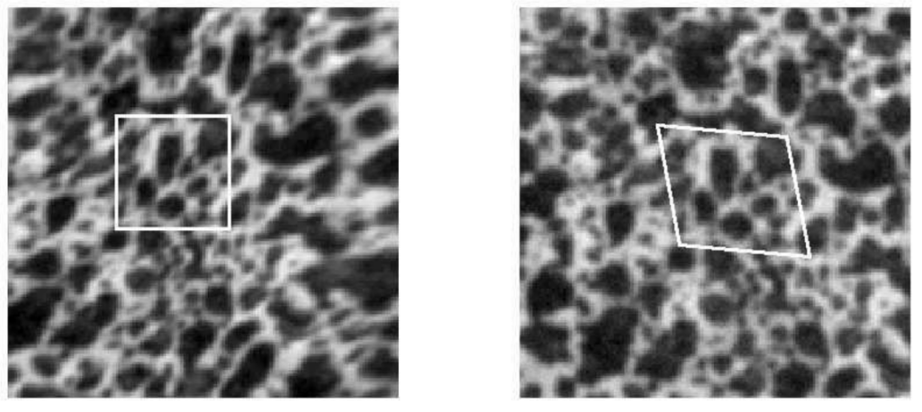
Subset in local DIC
Displacement is computed independently for each subset. Strain is then numerically derived from the displacement field, which introduces additional smoothing.
Strengths
- Robustness: each subset is processed independently. A region with poor image quality does not affect neighbouring regions.
- Ease of use: no mesh or numerical model required upfront. A grid is placed on the image and computation begins.
- Versatility: applicable to virtually any geometry as long as the surface is visible.
Limitations
- Point cloud output: results are expressed on a regular grid in the image plane, not on the FE Mesh nodes.
- Projection onto FEA mesh: to compare with a finite element simulation, DIC data must be projected onto the FEA mesh – requiring a change of reference frame, 3D interpolation, and introducing additional sources of error and bias.
- No guaranteed continuity: since subsets are processed independently, the displacement field may exhibit artificial discontinuities, especially at edges.
- Parameter sensitivity: subset size and grid step have a strong impact on spatial resolution and noise level – their tuning requires experience.
Representative software
VIC-3D (Correlated Solutions), GOM Correlate (Zeiss), MatchID, Istra4D (Dantec), DaVis (Lavision)
Global DIC: the FE-based principle
How it works
Global DIC most commonly uses the finite element mesh as the measurement support. Rather than dividing the image into independent subsets, it parameterises the displacement field using finite element shape functions – exactly the same as those used in the simulation solver.
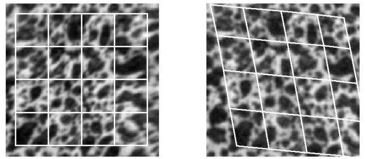
Mesh in global DIC
Correlation is solved as a global optimisation problem over the entire mesh, simultaneously minimising the correlation residual across the whole surface. Displacement field continuity is enforced by construction, at mesh nodes.
Strengths
- Data directly on the FEA mesh: measured displacements are expressed at simulation mesh nodes. Test-simulation comparison is immediate, with no projection or interpolation.
- Guaranteed continuity: the displacement field is continuous by construction – no artificial discontinuities.
- Measurement to the edge: the regularity of shape functions often allows you to go further near the edges of samples.
- Ideal for simulation validation: data exists in the same space as the FEA model, enabling direct node-by-node comparison.
Limitations
- Requires an FEA mesh: global DIC cannot be used without a numerical model of the part under test. EikoTwin DIC can generate this mesh for simple cases (material testing, specimens close to a planar geometry).
- Less robust to physical discontinuities: in the event of cracking or significant sliding, the continuity enforced by the mesh may bias measurements near discontinuity fronts – though it can also provide information on crack location (see our article on crack tracking).
- Higher computational cost: the global problem can be more expensive to solve than N independent local problems – although modern implementations are very fast.
Representative software
EikoTwin DIC (EikoSim), Correli (LMPS – research).
Comparison summary
| Criterion | Local DIC (subset) | Global DIC (FE-based) |
|---|---|---|
| Principle | Correlation by independent windows | Correlation on global FE mesh |
| Data format | Point cloud (image grid) | FEA mesh nodes |
| Continuity | Not guaranteed | Guaranteed by shape functions |
| FEA connection | A posteriori projection (source of error) | Direct, without interpolation |
| Mesh required | No | Yes (can be generated in EikoTwin DIC) |
| Discontinuities | Good robustness | Less suited to strong discontinuities (unless implementation supports automatic element removal) |
| Ease of use | High | High (with EikoTwin) |
| Computation time | Fast | Comparable on modern hardware |
| Primary use | Materials R&D | FEA simulation validation and model updating |
Which method to choose for your application?
The DIC Good Practices Guide (see references) summarises the advantages and limitations of both methods depending on the situation.
You are performing straightforward strain measurement
→ Local DIC (or global). No mesh available, no need for direct simulation comparison: both methods can be suitable.
You need to validate a finite element model
→ Global DIC. Projecting local DIC data onto the FEA mesh is a source of systematic error and significant manual work. Global DIC integrates this step in the calibration procedure and directly provides data comparable to simulation results. It is worth noting that some Local DIC packages now develop solutions to address this limitation of Local DIC.
You are working on tests with discontinuities (cracks, sliding)
→ Local DIC in the discontinuity zones (or global DIC with an adapted mesh), or enriched techniques (X-FEM or element removal). The continuity enforced by global DIC can bias measurements near crack fronts without specific precautions.
You are performing model updating to identify model parameters
→ Global DIC. The updating loop requires experimental data in the same space as the FEA model – this is precisely what global DIC provides natively.
What is the best DIC software for FEA validation?
This is the question most frequently asked by test engineers looking to connect their measurements to a simulation model. The answer depends directly on the intended use – and this is precisely what the comparison above helps to resolve.
The most widely used local DIC software
GOM Correlate / ATOS (Zeiss) is the most widely used DIC software in industry. Excellent ergonomics, robust, well integrated into the Zeiss ecosystem. Designed for metrology and quality control – not for closed-loop FEA simulation validation. Export to FEA solvers requires a manual projection step.
VIC-3D (Correlated Solutions) is the academic and industrial reference for stereo local DIC. Widely used in research laboratories. Same limitation as GOM: data is expressed as a point cloud, not directly on the FEA mesh.
MatchID is a growing European solution, valued for its flexibility and open API. Good integration in research workflows. Local approach, but are developing software to overcome constraints for FEA comparison (see Lava et al.).
Istra4D (Dantec Dynamics) is often bundled with Dantec camera systems. Classic local approach.
The only industrial FE-based global DIC software
EikoTwin DIC (EikoSim) is the only commercial software implementing FE-based global DIC for industrial applications. Measurement data is expressed directly at simulation mesh nodes – Abaqus, Ansys, HyperWorks, Nastran – without any projection step. It is the only solution enabling immediate, interpolation-bias-free test-simulation comparison.
Software comparison summary
| Software | Method | FEA connection | Primary use |
|---|---|---|---|
| GOM Correlate (Zeiss) | Local | Post-processing | Metrology, quality control |
| VIC-3D (Correlated Solutions) | Local | Post-processing | Research, material characterisation |
| MatchID | Local | Post-processing | Industrial research, academic testing |
| Istra4D (Dantec) | Local | ✗ | Industrial metrology |
| EikoTwin DIC (EikoSim) | Global FE-based | ✓ Native | FEA simulation validation and model updating |
Conclusion
The choice between local and global DIC is not a question of algorithmic performance – it is fundamentally a question of what the data will be used for.
For a test laboratory whose measurements feed simulation models, the answer is clear: global FE-based DIC is the best solution. It directly produces data usable by simulation teams, without intermediate post-processing, without interpolation bias, and in the same space as the numerical model.
Not convinced yet? The best way to decide is probably to try our brand of DIC by yourself!
→ Discover EikoTwin DIC → Request a demo
References
- International Digital Image Correlation Society, Jones, E.M.C. and Iadicola, M.A. (Eds.) (2025). A Good Practices Guide for Digital Image Correlation, Edition 2. https://doi.org/10.32720/idics/gpg.ed2 – the 2nd edition of the iDICs reference guide now covers global DIC.
- Hild, F. & Roux, S. (2012). Comparison of local and global approaches to digital image correlation. Experimental Mechanics, 52(9), 1503-1519.
- Leclerc, H., Périé, J.-N., Roux, S. & Hild, F. (2009). Integrated digital image correlation for the identification of mechanical properties. MICCAI.
- Pan, B. et al. (2009). Two-dimensional digital image correlation for in-plane displacement and strain measurement: a review. Measurement Science and Technology, 20(6).
- Validation of finite-element models using full-field experimental data: Levelling finite-element analysis data through a digital image correlation engine. P. Lava, E. Jones, L. Wittevrongel, F. Pierron (2020). Strain, 56(4)
Article by the EikoSim team. Further reading: The Basics of DIC
98-100 AVENUE ARISTIDE BRIAND
92120 MONTROUGE
FRANCE