Camera calibration: principles and procedures
- By Myriam Berny, R&D engineer at EikoSim
Using a multi-camera system for metrology and accurate measurements requires the calibration of the pixel coordinates of these cameras. They can be represented mathematically by a projection model in the form of a matrix, allowing the passage of the position of 3D points to their projection in 2D image space.
The process of estimating the parameters of the camera model, consisting of a set of intrinsic, camera model parameters, and a set of extrinsic external parameters, is known as the calibration algorithm.
In the following, we will first present the mathematical model describing a basic camera model, then the main families of calibration methods used in computer vision, and finally, the precautions to be taken to limit the errors made during performing camera models’ calibration, and ensure its success.
How to model a camera?
The geometric model of a camera, shown in Figure 1, is based on three elementary transformations. Their combination forms the so-called pinhole camera model [1].
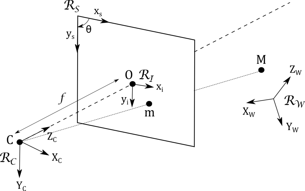
Figure 1 – Projection of the full image plane coordinates a pinhole camera model. 3D point on an image with a full image plane and pinhole camera model (adapted from [2]).
The position of a 3D point M of the camera coordinates the scene, defined in the world reference frame RW by its world coordinates (XW, YW, ZW), is expressed in the local coordinate system RC attached to the camera C with the local coordinates (XC, YC, ZC). This frame change constitutes the first transformation and depends only on three rotations and three translations.
This first transformation between the world homogeneous coordinates {Xw} = {XW, YW, ZW,1}T and the local homogeneous coordinates {Xc} = {XC, YC, ZC,1}T is represented by a 4×4 matrix denoted T.
It can be decomposed into a rotation matrix R (parametrizable for example, by three, rotation and translation angles) and a rotation and translation of vector t (defined by three components). Thus we have:
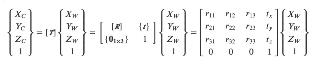
These six parameters (three angles, three translations) are called extrinsic parameters and therefore define the positioning of the camera coordinates and the image coordinates of the camera in 3D space.
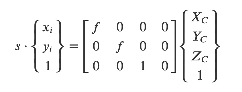
The second transformation corresponds to the projection of the 3D point M onto the retinal image plane itself, the image plane to which the local system RI is attached, into a 2D point m. It involves only the focal length f of the still camera lens and a scale factor s according to:
The last transformation expresses the homogeneous 2D coordinates {xs} = {xs ys, 1}T of the projected point m in the image sensor = frame RS and involves the image sensor: characteristics:
- the skew angle between the horizontal and vertical axes of the sensor, assumed to be equal to 90°;
- the position of the optical center
- the physical size of the pixel in both directions.;
The combination of the two previous transformations can be described through a 3×4 projection matrix K which is written:
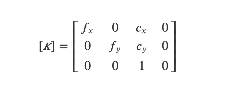
This projection matrix is therefore defined by four intrinsic parameters related to the calibrated camera: the horizontal (fx and vertical (fy) focal lengths in pixels and the position (cx,cy) in pixels of the optical center in the whole image plane.
The complete projection matrix M describing a camera is thus composed of an extrinsic parameter matrix T and an intrinsic parameter matrix K, so that:

The projection matrix M can thus be expressed “implicitly” as a 3×4 matrix containing 12 terms (mij) or “explicitly“, via the 10 independent extrinsic and intrinsic parameters presented previously. In its explicit form, M is then written:
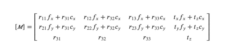
The purpose of the calibration of a camera is to estimate internal parameters and extrinsic parameters represent those of its projection matrix M. When the procedure aims at identifying the mij terms, it is called implicit calibration, while it is called explicit calibration (or “strong” calibration) when it identifies the extrinsic and intrinsic calibration parameters.
In the camera model introduced earlier, distortions are not taken into account. Distortions, which are due to imperfections in the optical system such as defects in the shape and positioning of the camera lenses, will deflect the light rays and beams and thus induce a positional deviation for multiple images of light rays at the projected point compared to an ideal model [2]. It is then possible to complete the camera model by introducing the three distortions that generate the most effects left image behind, namely radial, decentering and prismatic distortions (see Figure 2), induced by defects in curvature, lens parallelism and coaxiality of the optical axes.
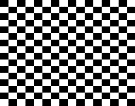 | 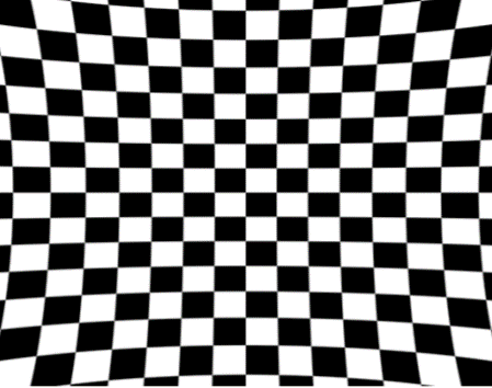 | 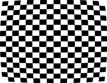 | 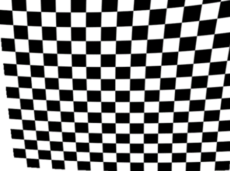 | 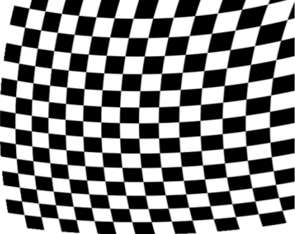 |
| (a) | (b) | (c) | (d) | (e) |
In the following section, the main families of camera calibration and procedures that aim to perform camera calibration and determine the parameters of the camera model will be presented.
How to carry out a camera calibration?
The purpose of the calibration pattern of a camera is to determine the parameters (explicit or implicit, camera matrix) of the camera intrinsic matrix and camera parameters its associated projection matrix. Several methods exist that the calibration patterns can be grouped into three main categories, described below:
- Calibration thanks to a target, which is the classic approach to calibrating a camera;
- Self-calibration, which uses the a priori knowledge of the nominal geometry of the imaged object to determine the camera parameters;
- Hybrid calibration, which combines the two previous approaches to identify separately the intrinsic and extrinsic parameters of the camera.
The calibration with a target is based on the use of a 3D object of known geometry (called a calibration target) and its image acquired by the camera [1, 2]. This calibration object has specific 3D points on its surface, of known positions.
They may correspond to the intersection of vertical and horizontal lines when the target is a grid (or a chessboard) or to the center of circles when the calibration object is composed of points.
The position of these 3D points on the image of the calibration target is often obtained through automatic image analysis procedures [4].
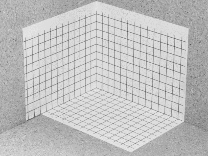 | 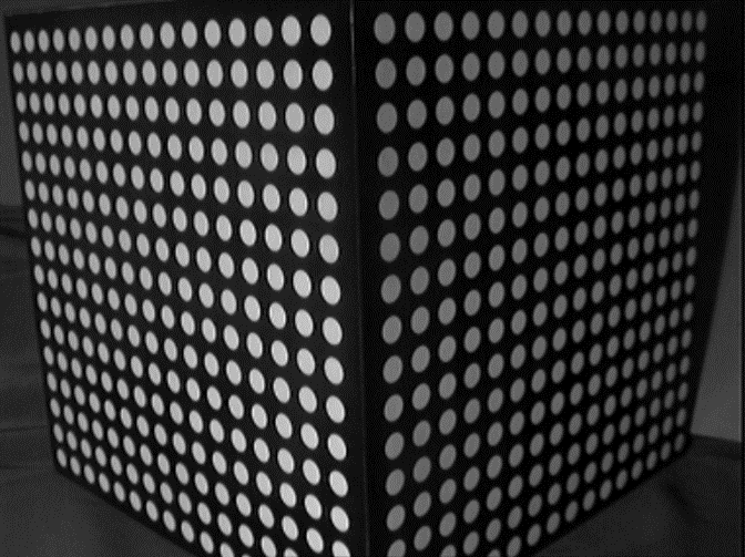 | 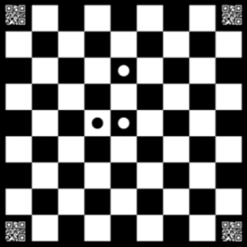 | 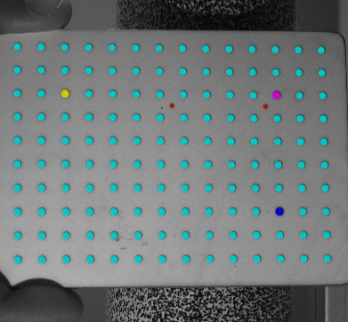 |
Thus, the algorithm consists in optimizing the projection matrix until the quadratic sum of these reprojection errors is minimized. With this type of approach, distortion coefficients of the projection matrix can be identified either implicitly or explicitly.
Distortion characteristics can also be identified for the most complex models [9, 10]. In the case of a stereovision system (i.e., with 2 cameras), this approach will independently identify the parameters (intrinsic and extrinsic) of lens distortion in one of the two cameras, which will become the “master camera” [5].
The second camera, called the “slave camera“, will have its intrinsic parameters identified via the calibration target and its extrinsic parameters will be defined in relation to the position of the master camera, through the determination of a linear transformation matrix allowing to go from camera 1 to camera 2.
This matrix can be predefined by the stereovision or coordinate system, supplier for systems where the relative position of the cameras is fixed, or re-identified from the calibration object images. Since the targets used in coordinate system for a calibration must occupy a 3D space, they must be 3D or, if they are flat, they must be moved in space using translation and rotation motions [1, 11].
With this type of calibration, it is necessary to acquire at least 50 images of the target [12, 13] to be able to calibrate the stereovision system and minimize the effect of acquisition noise and calibration errors.
Furthermore, since the camera calibration refers the camera matrix and target is external, it is not possible to recalibrate the cameras during the experiment, which may be necessary if the cameras move inadvertently (movements of the camera tripod, gradual unscrewing of the cameras…).
The second type of calibration is called self-calibration [14] and is used in particular by the so-called “global” stereocorrelation approaches [15], such as the one proposed by EikoTwin DIC. It uses the whole test piece as a calibration object and this thanks to a dense description of the object (i.e., the position of each point of the piece is parameterized and can be determined through a mathematical model [16]).
One of the possible descriptions is the finite element mesh [17, 18]. Consequently, the entire mesh is used as specific points to minimize reprojection errors and to identify the parameters of the camera models (and not just the particular points of a calibration target).
The entirety of this mesh will be associated with normalized image coordinates, the entirety of normalized image pixel coordinates the speckled test sample visible on the images acquired by the cameras, and by extension the entirety of the pixel coordinates the texture of the sample (speckle pattern). The goal of the procedure is to simultaneously find the implicit parameters parameterizing the cameras (without hierarchy between the cameras), by minimizing the difference in gray level between the projection of the 3D points via each of the cameras (using its projection model to be optimized) and a reference image common to all the cameras (built from all the cameras).
The 3D points correspond to evaluation points constructed for each element of the mesh (equi-partitioned subdivisions within the element) where the gray levels and gradients will be evaluated to minimize the reprojection errors.
Thus, with this approach, it is possible to calibrate a stereovision system with a single pair of stereo images, while being robust to noise thanks to the multiplicity of evaluation points induced by the dense description of the tested piece. Moreover, the position of the cameras is expressed in the reference frame of the sample and it is possible to recalibrate at will the cameras during the test by using the acquired images.
However, one of the limitations of this approach by self-calibration is the three-dimensional nature of the sample to be tested, which remains a condition to avoid the mathematical singularities of the calibration of a camera [9]. For cases where the tested object does not respect these geometric conditions (case of a flat sample or a solid of revolution such as a cylinder), it is recommended to resort to hybrid calibration, which is also a procedure proposed by EikoTwin DIC.
This approach combines the use of a ChAruCo calibration object (of well-known geometry) and a global stereocorrelation approach (by self-calibration). The use of the ChAruCo target allows to explicitly set some of the projection parameters to fixed values, namely the intrinsic parameters of the camera (matrix K), and to make the identification of the other extrinsic parameters represent the camera matrix, T (in implicit form) more reliable by self-calibration. For more details, the description of this approach, its advantages and conditions of application are presented in our blog post “Hybrid calibration: a robust alternative to self-calibration”.
How to avoid camera calibration errors?
Poor camera calibration very often leads to errors in the measurement of displacements and, consequently, of deformations. To ensure proper calibration, it may be appropriate to acquire images of rigid body motions lens distortion (translation) of known amplitude and verify that the displacement measurement is consistent with distorted image.
In addition, several precautions can be taken to ensure that the calibration phase is successful:
- Make use of “Virtual Testing“, by preparing the test in advance virtually. EikoTwin Virtual uses the visualization tool Blender to determine camera positioning in advance and to optimize it in order to have a good calibration to measure the expected displacements (from a finite element simulation). More details about these aspects can be found in our article “Preparing your Digital Image Correlation test with Blender” available on our blog.
- If this phase of virtualization can not be carried out, it is advisable to anticipate possible problems by adapting the position of the cameras on the day of the experiment, by highlighting additional 3D points in the FOV, or by using hybrid calibration in order to make the calibration of the cameras more reliable. Several criteria have been identified to estimate the reliability of the calibration beforehand, see our article “Mastering self-calibration with Eikotwin DIC”
Conclusions
The calibration of cameras is the first step of any analysis by digital images correlation and remains a step to be carried out meticulously, especially when precise measurements are sought (of shape, displacements or deformations).
All existing approaches aim at minimizing the reprojection errors between a characteristic linked to the projection of specific 3D points (position, gray level value) and their real characteristic on the image. These points can then be remarkable points on a calibration target or evaluation points associated with a surface mesh in the case of global approaches.
EikoTwin DIC proposes calibration procedures by self-calibration and by hybrid calibration in order to identify in a robust and simultaneous way the projection matrices of the cameras by using a single pair of images (and about twenty target images if the hybrid calibration is chosen).
These procedures have many advantages (simplicity, calibration in the reference frame of the tested sample, robustness to noise, possibility to simultaneously calibrate a multi-view system…) and can be adapted to any type of experiment.
By preparing calibration images for the test beforehand via virtualization or by checking that some criteria are met, it is then possible to ensure that the cameras are properly calibrated, which is a prerequisite for reliable measurement of displacements and reduction of errors for kinematic measurements.
References
[1] O. Faugeras, Three-dimensional computer vision: a geometric viewpoint. Cambridge, MA (USA) : MIT Press, 1993.
[2] M. Sutton, J. Orteu, et H. Schreier, Image correlation for shape, motion and deformation measurements: Basic Concepts, Theory and Applications. New York, NY (USA) : Springer, 2009.
[3] G. Besnard, Caractérisation et quantification de surfaces par stéréocorrélation pour des essais mécaniques du quasi statique à la dynamique ultra-rapide. PhD thesis (in French), ENS de Cachan, 2010.
[4] P. Brand, Reconstruction tridimensionnelle d’une scène à partir d’une caméra en mouvement : de l’influence de la précision. PhD thesis (in French), Université Claude Bernard (Lyon I), 1995.
[5] D. Garcia, Mesure de formes et de champs de déplacements tridimensionnels par stéréocorrélation d’images. PhD thesis (in French), Institut National Polytechnique de Toulouse (INPT), 2001.
[6] J. Heikkilä, “Geometric camera calibration using circular control points”, IEEE Transactions on Pattern Analysis and Machine Intelligence, vol. 22, pp. 1066 – 1077, 2000.
[7] Original image from: https://dantecdynamics.com/wp-content/uploads/2019/11/2.-Calibration-target.png
[8] Original image from: https://correlatedsolutions.com/wp-content/uploads/2016/09/3D-Calibration.jpg
[9] R. Tsai, “A versatile camera calibration technique for high-accuracy 3D machine vision metrology using off-the-shelf TV cameras and lenses”, IEEE J. Robotics Autom., vol. RA- 3, no. 4, pp. 323–343, 1987.
[10] J. Heikkilä et O. Silvén, “A four-step camera calibration pattern and procedure with implicit image correction”, IEEE International Conference on Computer Vision and Pattern Recognition, pp. 1106–1111, 1997.
[11] Z. Zhang, “A flexible new technique for camera calibration”, IEEE Trans. Pattern Anal. Machine Intell., vol. 22, no. 11, pp. 1330–1334, 2000.
[12] M. Sutton, “Computer vision-based, noncontacting deformation measurements in mechanics: A generational transformation”, Appl. Mech. Rev., vol. 65, no. AMR-13-1009, p. 050802, 2013.
[13] International Digital Image Correlation Society, A Good Practices Guide for Digital Image Correlation, Jones, E.M.C. et Iadicola, M.A. (Eds.), 2018.
[14] O. Faugeras, Q. Luong, et S. Maybank, “Camera self-calibration: Theory and experiments”, dans Proc. 2nd ECCV, pp. 321–334, Springer-Verlag, 1992.
[15] J.-E. Dufour, F. Hild, et S. Roux, “Shape, Displacement and Mechanical Properties from Isogeometric Multiview Stereocorrelation”, J. Strain Analysis, vol. 50, no. 7, pp. 470–487, 2015.
[16] F. Hild et S. Roux, “Procédé de mesures tridimensionnelles par stéréo-corrélation utilisant une représentation paramétrique de l’objet mesuré”, Dec. 6 2013. Patent n°FR2991448.
[17] J.-E. Dufour, B. Beaubier, S. Roux, et F. Hild, “Displacement measurement using CAD-based stereo-correlation with meshes”, in ICEM conference, 2014.
[18] L. Dubreuil, J.-E. Dufour, Y. Quinsat, et F. Hild, “Mesh-Based Shape Measurements with Stereocorrelation: Principle and First Results”, Exp. Mech., no. 56, pp. 1231–1242, 2016.
98-100 AVENUE ARISTIDE BRIAND
92120 MONTROUGE
FRANCE