Calibration of material parameters from a single test: workflow
By Florent Mathieu, CEO of EikoSim. Images and data – credits IRT St Exupéry
How can you perform calibration of several material parameters with a single test? Here’s a guide.
In a previous article, we explored the possibilities offered by lattice structures and showed how it is possible to measure these complex kinematics using Digital Image Correlation. That article ended with a comparison between measured and simulated displacement fields.
In our practice, we frequently find ourselves in a situation where the simulation model is not directly validated by measurements taken on the prototype. Several sources of error can explain these differences:
- choice of behavior law or material parameters: even if the law has been validated in material tests, it may be used outside its field of validity when we move on to calculating the structure or substructure.
- simulated geometry: choices to simplify geometry or mesh may explain a difference in behavior. For example, a difference in the thickness of a thin wall, or local manufacturing defects in the prototype compared to the CAD model.
- choice of boundary conditions: it’s very common to use simplifying assumptions when modeling boundary conditions (zero displacement, displacement or force applied perfectly in one direction in space). Spoiler alert: true embedding does not exist!
- choice of contact models: similarly, an initial approximation of contact between two parts, made for simplicity’s sake or to reduce calculation costs, can later prove problematic.
Our experience shows that in structural calculations, as in material testing, boundary conditions can play a role to first order: it is therefore necessary to take them into account, or else end up with completely wrong material law parameters! The example below shows how some of these factors can be taken into account when performing material calibration with the EikoTwin Digital Twin software in the case of the lattice structure tests already presented before. This work was carried out with the IRT Saint Exupéry as part of the LASER project (2019-2021, supported by the PIA – “programme investissement d’avenir”, with Safran, Ariane Group, Thales Alenia Space, Altran Technologies and SIMAP).
Issue 1: using realistic boundary conditions
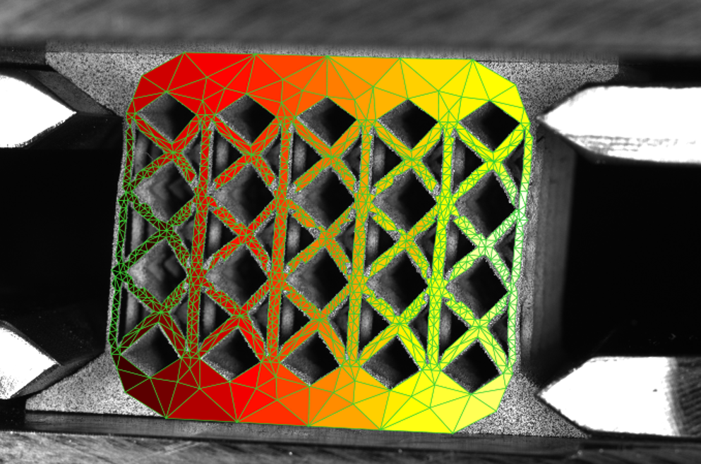
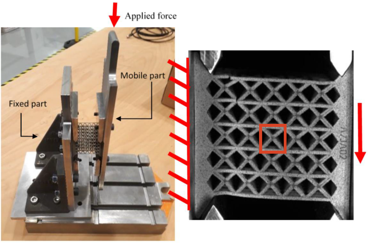
The test in question here is a non-standard test (between shear and embedded-free bending) on a BCCZ lattice structure sample (see figure below). The elements placed at the left and right of the sample hold the structure, and the rigid plate at the right of the photo moves in such a way as to stress the structure in either bending or shear, depending on its length.
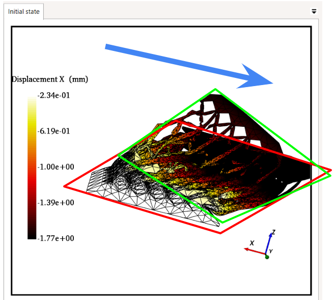
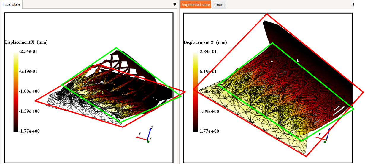
At the end of the previous article, there was a clear difference between the measured and simulated displacement fields, as can be seen in the figure below. The exaggeration (here by a factor of 15) of the deformation of the structures reveals the differences between the kinematics of the surface of the physical prototype (measured, in green) and the virtual prototype (simulation, in red). The direction of loading is shown in blue on the screen. This figure shows a greater displacement of the lower part of the sample to “accompany” the movement, and also a rotation (the shear appears less significant and more localized).
Solution: DIC-based control of boundary conditions
With the EikoTwin Digital Twin software, it is possible to take this into account and directly modify the simulation model concerned. By selecting zones, it is possible to recreate sets of nodes in the volume model and apply the displacement measured on the surface, resulting in what we call an “augmented simulation model”.
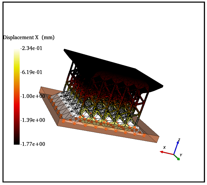
In the end we can obtain in a much better agreement between simulation and measurement, as shown in the figure below. This model error could have been hastily dismissed as a defect in the material law, since its identification is the aim of this test.
Issue 2: Calibrating the constitutive model
Once the boundary conditions have been adjusted, it is possible to identify material parameters. In Digital Twin, this identification is based on sensitivity studies of the simulation to model parameters. Here, these parameters are those of the behavior law, but it is possible to use others in the software.
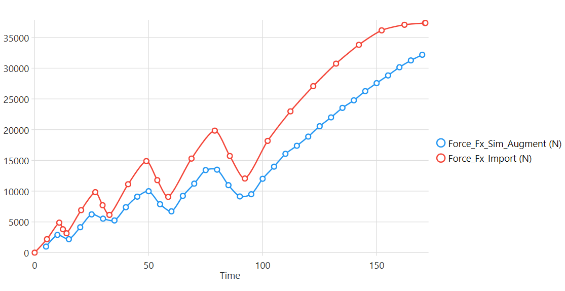
After resetting the boundary conditions, we can see that the reaction force signal (extracted from the simulation at the nodes driven by the newly-formed boundary condition) shows a significant difference with the measured force (see below).
The software then calculates simulation sensitivities to the parameters considered (here, the parameters of an elasto-plastic power law). The by-products of this analysis are the sensitivity signals according to the criteria chosen here to create the deviation functional between test and calculation. In this case, it’s the combination of the force and the displacement fields.
The figure below shows, for example, the sensitivity of force to a 5% variation in Young’s modulus. These signals are then combined to create a unique problem of minimizing the test-calculation deviation. Also shown in the figure below are the correlations between the parameters in the sense of these criteria, which can be useful in determining the couplings that exist between these parameters.

Solution : automated model calibration
Once these analyses have been carried out, the identifiable parameters are determined. The iterative algorithm then takes charge of minimizing the test-calculation deviation, here in both displacement and force. As can be seen below, the error in force is predominant here (displacement being well controlled thanks to the measured boundary conditions). The Digital Twin algorithm enables us to rapidly approach a minimized solution. We can then observe the evolution of the parameters considered in the analysis, as well as their final values.

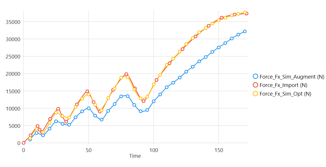
Once the algorithm has converged, we can also observe that the effort of the optimized simulation matches the measured effort perfectly:
This example is an original application of a Digital Twin that enables the direct identification of 4 parameters of a complex structure, which would have been very complex with traditional measurement techniques and without knowledge of the structure’s actual boundary conditions.
This type of example also provides some answers to the classic question: can we do without physical testing? Certainly, the characterization of materials and lattice geometries poses problems, but we can imagine characterization campaigns that will eventually come to grips with all combinations of materials and structures. On the other hand, given this example, it is questionable to think of representing a structure without having an excellent knowledge of its boundary conditions, and this is often a more complex problem than that of the calibration of material properties.
In the application presented in this article, the material in question is presented “in the structure”, which combines both the behavior of the material and its structural component. This makes it possible to combine these effects and characterize them in a single test.
📖 This article is part of our Complete guide to digital image correlation.
98-100 AVENUE ARISTIDE BRIAND
92120 MONTROUGE
FRANCE