How to preview your test using Blender software?
- By Pierre Baudoin, R&D engineer of EikoSim
Blender as a supporting tool for 3D DIC tests
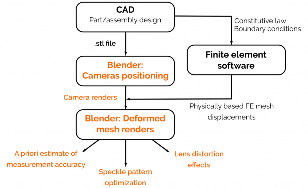
Have you ever heard of Blender to preview a mechanical test? Blender is a comprehensive, open-source, cross-platform 3D creation suite that can be used to create photo-realistic renders, animations, or even full-length movies. Blender’s render engine can produce physically based photo-realistic renders of any 3D environment. In particular, it can be used for the virtual design of experiments simply using CAD files, as shown by LMT researchers (ENS Paris-Saclay, France) in [1]. In this context, the typical workflow consists in the following 4 steps:
- Part design. This can be done using any CAD software, or Blender itself. The part should be converted to a 3D surface mesh before importing (e.g, .stl file).
- Texturing. Once the part mesh has been imported in Blender, a realistic texture must be applied to the part mesh.
- Camera positioning. Blender’s fine-tuned camera management allows to anticipate experimental fields of view (FOVs) with accuracy. To minimize measurement uncertainty, the automation of camera positioning can also be considered [1].
- Rendering. Once the parts have been textured and the cameras positioned, Blender can generate realistic renders of the camera images.
Following the previous steps before any real-world experiment allows to verify the feasibility of any experimental test, and to adapt the choice of equipment (camera, lenses, lighting, etc.) if required.
Virtual testing: combining Blender with finite element simulations
If we have a rough estimate the constitutive model of our test sample and boundary conditions, we can even go a little further in the pre-visualization of the test. Textured meshes can be deformed in Blender, all the user needs to provide is a node-by-node displacement field. We can then use the displacements fields produced by a finite element simulation to deform the mesh in Blender and generate renders of the deformed part (fig.1).
In anticipation of the actual experiment, this approach is interesting because it lets us test the influence of many parameters on the measurement accuracy. For 2D-DIC, it is common to evaluate the precision of an algorithm using virtual tests on digital images [2]. Blender is very useful when it comes to extending this approach to 3D measurements, because handling 3D texture deformation is one of its core features. To cite but a few parameters, this approach can be used to evaluate the influence of lens distorsion, and speckle pattern shape and size on measurement accuracy.
A simple example based of a test preview in Blender with an elastic simulation
Let’s say we want to carry out a bending test on our wing model (fig.2). We can introduce this loading in Abaqus (fig.2a), and assuming its behavior to be linear elasticity, we can compute the displacement fields for a 2.5 mm displacement exerted near the tip of the wing.
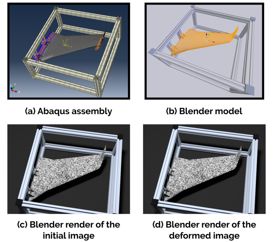
After a quick reformating, the FE meshes were imported in Blender (fig. 2b). We then applied a speckle pattern texture to the mesh. At this point, we placed two cameras around the model, and made a render of the undeformed state (fig.2c, only the render of the first camera is shown, for brevity). Finally, we used the displacements computed in the FE simulation to deform the mesh in Blender, and generated renders for the deformed images (fig.2d, only the render of the first camera is shown). In another article, the use of Blender is detailed in more details in the case of a complex structure.
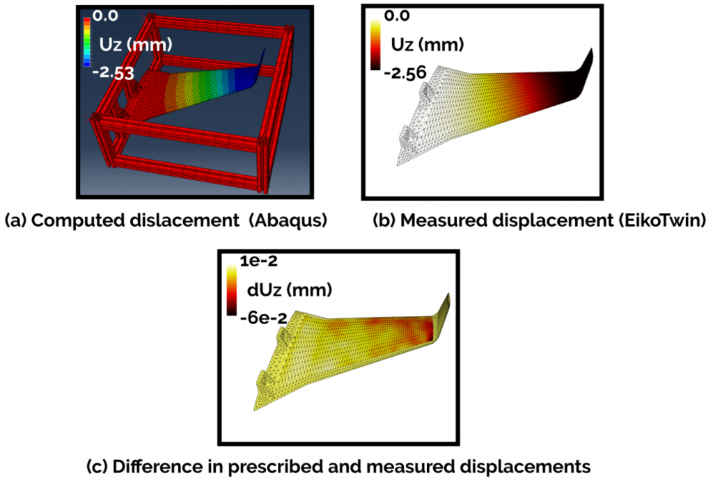
We can then use EikoTwin DIC to compute 3D surface displacements from these pairs of virtual images. Even though no particular care was taken in optimizing the camera positions or tuning the speckle pattern, the bending motion measured by EikoTwin DIC is quite close to the displacements prescribed in the simulation (fig.3a-b). Using the ‘load FE result’ feature in EikoTwin, we can also take a look at the spatial distribution of displacement errors, which confirms the good accuracy of the measurement (fig.3c).
Moving forward…
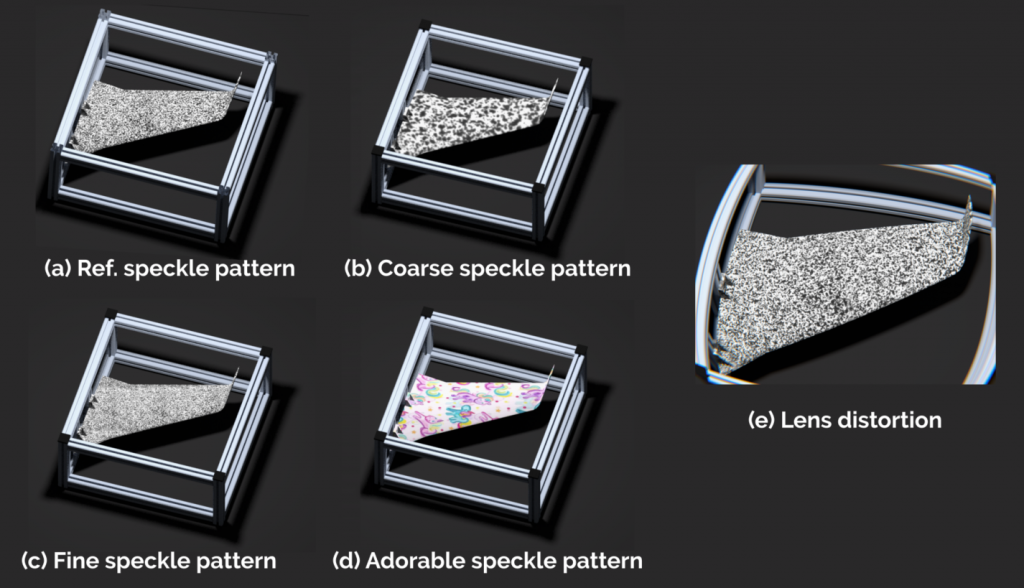
In the future, we plan on expanding on the previous test to further quantify our measurement accuracy depending on experimental conditions (fig.4), thanks to test preview in Blender. For a given FE mesh and geometry, what would be the ideal texture to apply in our experiment? What would be the ideal speckle size (fig. 4a-c) or shape (fig.4d) of this pattern? What would be the impact of severe lens distortion on the measured displacements (fig. 4e)? Look forward to more blog posts on the subject!
References
[1] Vitse, Matthieu, et al. “Design and optimization of a multi-camera structural test using pre-visualization.” BSSM 13th International Conference on Advances in Experimental Mechanics (2018)
[2] Bornert, Michel, et al. “Assessment of digital image correlation measurement errors: methodology and results.” Experimental mechanics 49.3 (2009): 353-370.
98-100 AVENUE ARISTIDE BRIAND
92120 MONTROUGE
FRANCE