What is a good dic speckle pattern?
- By Clara Minguet, Research engineer at EikoSim
Concerned about making a new speckle pattern for your DIC experiment? In another article, we talked about the different techniques for creating a speckle pattern in digital image correlation, including the ability to vary the size and nature of the spots projected on the piece.
But what size should your speckle pattern be?
There is no “good” or “bad” speckle, or rather one cannot judge the quality of one’s speckle without knowing the intended application.
For example, if you measure an area 10mm wide or 1m wide, the paint spots (if the paint is used) should not be the same.
Three parameters are at work:
- The size of the observed area;
- The sensor size of your cameras;
- The physical size of the elements used.
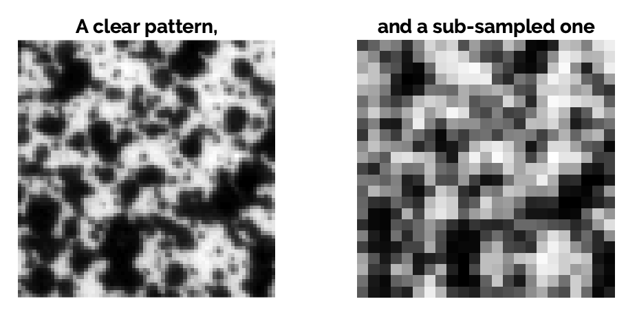
Let’s start at the beginning: the speckle spots must be clearly visible in the image. If they are too small, the spots will not be detected correctly by the image correlation algorithm, and it will be seen as a characteristic effect of subsampling (aliasing).
Therefore, a minimum spot size of 4 pixels in diameter is recommended.
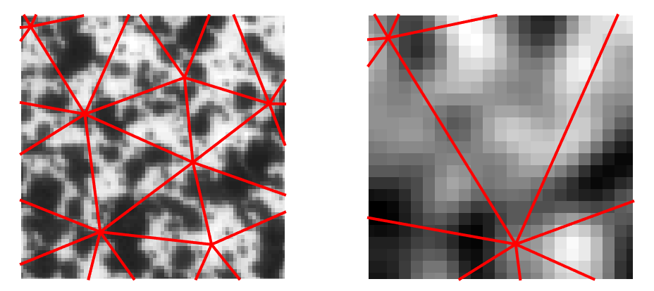
It must also be checked that the elements used are not too small for the intended application. If an element does not cover enough area in pixels, the associated measurement uncertainty will be much higher.
It is recommended that once positioned in the image, each element should contain at least 3 to 4 speckle spots.
It is assumed here that you are using a “global” image correlation software (and, therefore, a mesh). To decide what is the ideal size of spots and elements, there are two solutions:
- Either you use a mesh from a simulation to which you have to compare the results, in which case the element size is imposed and the spot size can be deduced from it. If the elements are too small to make a correct measurement, then you will have to get around the problem by modifying the mesh or using a regularization technique.
- Either you have the freedom to create your mesh, and then you can create it according to the resolution of the camera.
Finally, one must also take into account the sensor size of the cameras used. Together with the size of the observed area, this defines the “physical pixel size”, or pixel/millimeter correspondence.
This will naturally depend on the lens used for the measurement. Do not hesitate to consult our article on the choice of hardware if you need it.
At EikoSim, to simplify our life and still apply these rules to the letter, we have created a simple spreadsheet to prepare the tests when we have to create a speckle pattern for DIC.
Perhaps it can be of use to you? If so, please feel free to retrieve it here.
If the test configuration is complex, or if you want to test several configurations before the day of the trial, we have also used the Blender software to prepare the test setup.
98-100 AVENUE ARISTIDE BRIAND
92120 MONTROUGE
FRANCE