Thermal plugins from the EikoTwin suite
- By Clara Minguet, Research engineer at EikoSim
In order to meet the specific needs of customers and to extend the use of the EikoTwin software suite to other fields of activity, EikoSim has developed two new optional plugins: the DIC and DT thermal plugins. As their names suggest, DIC thermal plugin can be used in EikoTwin DIC software, and DT thermal plugin in EikoTwin Digital Twin software.
DIC thermal plugin enables the measured temperature field to be displayed directly on the simulation mesh in EikoTwin DIC. DT thermal plugin enables the creation of an augmented simulation with measured thermal boundary conditions in EikoTwin Digital Twin.
The use of these plugins is, in particular, interesting for tests involving thermal stress potentially coupled with mechanical stress.
DIC thermal plugin in EikoTwin DIC
Importing images
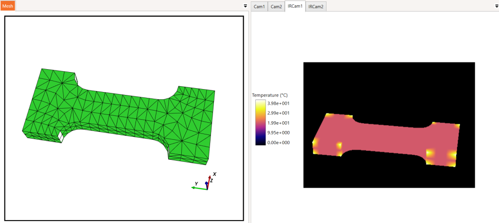
After installing the plugin, the user can now, in EikoTwin DIC software, import images in .mat format (Matlab) taken by an infrared camera (see Figure 1).
Two families of IR images can be read by DIC thermal plugin. They differ in the type of data provided by each pixel in the image:
- Digital Levels (DL),
- Temperatures in °C.
Digital Levels correspond to raw data recorded by an IR camera (accumulation of the photon flux on the camera sensor). As for temperatures, they are computed by the IR image acquisition software by converting raw data (DL) into temperatures using a conversion law associated with the IR camera and several parameters.
Among these parameters are camera parameters (wavelength range, camera gain…), acquisition parameters such as integration time, and a material parameter, emissivity. For most acquisition software, this emissivity is assumed to be constant on the temperature range, set at a user-provided value. This assumption is often true once the material does not undergo a high-temperature gradient.
Thus, in order to make the measured temperatures more reliable for materials whose emissivity varies with the temperature and that are submitted to significant thermal gradients, it is possible to import IR images containing data in DL and let DIC thermal plugin determine the transfer law that enables the conversion of Digital Levels into temperatures (in °C).
To import raw images in Digital Levels, the user must provide the software with the parameters of the camera (supposed to be monochromatic): the wavelength, the integration time, as well as the coefficients s and DL0 determined during the calibration of the IR camera by a black body.
The user must also supply the evolution of the emissivity of the material of the studied part, determined beforehand, depending on the temperature. Thus, from these data, DIC thermal plugin will estimate the conversion law between Digital Levels and temperatures (in °C).
The user can also provide the software with the emissivity uncertainty for images in Digital Levels, and whatever the image type, the thermal noise of every camera is parametrized by the following formula:

These parameters are used by the software to compute the thermal covariance matrices that can be exported later on. If the user does not want to retrieve these matrices, he can then leave the default values of uncertainty and noise.

Post-processing images
Post-processing of IR images in EikoTwin DIC is identical to that of visible images. As a reminder, first, the user imports the simulation mesh, chooses the measurement mesh then performs a pre-calibration by clicking points on the image and the mesh.
However, a distinguishing feature of IR images is the inaccurate way they describe the rugged nature of the part (see Figure 1) because the visible contrast in IR images comes from a real difference in temperature or a significant difference in emissivity. Therefore, some distinctive elements from the part surface easily noticeable in a visible image will not be in an IR image.
A traditional method to overcome this issue is the use of reference images. Indeed, after having definitively validated the configuration of the test and its environment, the user takes some images at rest with the thermal cameras by heating the distinctive elements from the part surface not visible in the IR images.
Importing these images in EikoTwin DIC in the “Pre-Calibration” tab will highly simplify the click of points on the images (see Figure 2).
The following step of calibration remains identical to the standard procedure.
Finally, in the “Displacement” tab, DIC thermal plugin enables the compute of temperatures at each mesh node (see Figure 3).
The obtained temperature field can be displayed directly on the simulation mesh, and the difference in temperature between measurement and simulation if the user imports a thermal or thermo-mechanical simulation result.
In the context of a kinematic and thermal measurements coupling, these data are measured from every IR image on the deformed mesh.
It is also possible to use DIC thermal plugin with only IR images but in this case, the fields will be provided on the initial mesh. Lastly, the measured temperatures can be exported in .csv or .vtu format.

A final feature specific to DIC thermal plugin is available in the “Sensors” tab of the software.
The user can create a virtual sensor of types “Thermocouple” or “Pyrometer” and display the data in a graph (see Figure 4).
A “Thermocouple” sensor measures temperature at one node of the mesh. The “Pyrometer” sensor performs a mean of the temperatures at the nodes included in the mesh area defined by the user-chosen radius.

DT thermal plugin in EikoTwin Digital Twin
After installing the plugin, the user can load in EikoTwin Digital Twin a project post-processed beforehand in EikoTwin DIC with DIC thermal plugin. One can note that to be able to perform post-processing in EikoTwin Digital Twin with the associated plugin, it is necessary to have displacement measurements in addition to the temperature measurements.
The available actions with the DT thermal plugin in the first tab of the software remain the same as those described previously for the other thermal plugin in the “Displacement” and “Sensors” tabs of EikoTwin DIC.
In the “Boundary conditions” tab, DT thermal plugin enables creating boundary conditions in temperature from the measured data. Thus, the user can impose in Abaqus simulation the temperature at the surface of the test sample on chosen nodes for which thermal measurements are available.
The new model, augmented with the experimental thermal boundary conditions, can then be exported.
The rest of the post-processing in EikoTwin Digital Twin remains unchanged from the standard procedure.
If you are interested in the thermal plugins, do not hesitate to reach your contact at EikoSim or to contact us via the contact interface of our website.
References
[1] M. Berny, High-temperature tests for ceramic matrix composites: from full-field regularised measurements to thermomechanical parameter identificationl parameter identification. PhD thesis, Université Paris-Saclay, 2020.
98-100 AVENUE ARISTIDE BRIAND
92120 MONTROUGE
FRANCE