How ArianeGroup improves simulation credibility with EikoTwin and DIC
- By Pierre Baudoin, R&D engineer at EikoSim
Simulation credibility is a key aspect of the Virtual Testing concept. As the European leader in space launchers, Ariane Group participates with EikoSim in multiple Research and Development projects, including a RAPID R&D project (“MUTATION”) funded by the Direction Générale de l’Armement.
This project aims at developing an industrial platform for test-simulation dialogue to meet the challenges of faster and safer development by improving the technical skills of modelling and simulation device credibility and simulation of real life at high levels of fidelity.
The Galileo dispenser project
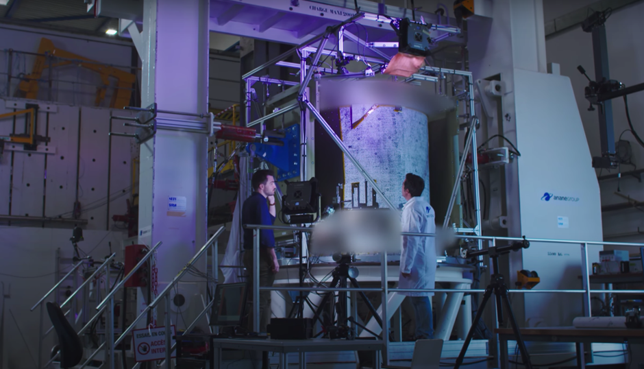
Within this R&D project, one of the key use cases was the qualification test of the Galileo Dispenser in the Ariane 6 version.
A dispenser is a system placed under the launcher fairing, which is designed to release one or several satellites during the launcher mission and to put them into orbit.
The test is performed on a flight model, which means that only qualification load cases are applied to the structure, but without ever reaching failure.

Digital continuity as a path to simulation credibility
The MUTATION project was the occasion to integrate Digital Image Correlation (DIC) in the data fusion approach to evaluate its benefits for structural simulation in a large structural test context.
Overall, the dispenser test was the first end-to-end project that involved every tool that was developed within the project.

DIC post-processing by EikoSim
Calibration Validation
Hybrid calibration was used to carry out pre-calibration for the more zoomed-in ZOIs (ZOI n°1 and n°3). Markers were disposed on the sample surface at precise coordinates so that the link between the model coordinate system and measurement frame could be established.

The speckle pattern was sprayed onto the sample surface using paint mat paints, according to the virtual study’s specification. Fig 4c shows that the retained method indeed provided us with enough texture under the reprojected elements.
Calibration was validated with the following observations:
→ Excellent reprojection, high fidelity in the simulation of the FE on the images, low fidelity in simulation RMS on reprojection error computed post-pre-calibration.
→ What could be validated as a normal shape error derived from the EikoTwin platform’s self-calibration procedure? Strain gauge wires could clearly be identified in the residual field and in the shape error, proving the software’s ability to take them into account.
Results and post-processing of full-field measurements
DIC monitoring was used for all load cases. Images were taken regularly during the tests, and extra images were acquired during loading plateaus. We will focus on experimental results on the plateau corresponding to the maximum load of the first test configuration in the present paper.
For this plateau, it was critical to ensure credibility (i.e., that the measured strain fields and the FE strain fields matched closely in terms of strain localizations) but also to ensure that local strain values remained admissible with respect to structural integrity.
Results and post-processing of full-field measurements
DIC monitoring was used for all load cases. Images were taken at regular intervals during the tests, and extra images were acquired during loading plateaus. We will focus on experimental results on the plateau corresponding to the maximum load of the first test configuration in the present paper.
For this plateau, it was critical to ensure simulation credibility (i.e., that the measured strain fields and the FE strain fields matched closely in terms of strain localizations) but also to ensure that local strain values remained admissible with respect to structural integrity.

Although local differences could be observed between the measured and simulated fields (see Fig 5), an generally good agreement was found between the experiment and simulation. Strain localizations were correctly anticipated, and strain levels remained acceptable.
In fact, since both strain fields are computed using the exact same convention and expressed at the same physical location, a quantitative comparison was also performed (fig 6a). Mainly, the strain field difference shows that differences arise locally, in the vicinity of strain concentrations. Overall though, the difference between the two fields is of the same order of magnitude as measurement uncertainty (i.e., no significant difference across most of the FOV for test simulation differences). Credibility can be confirmed from this kind of map.
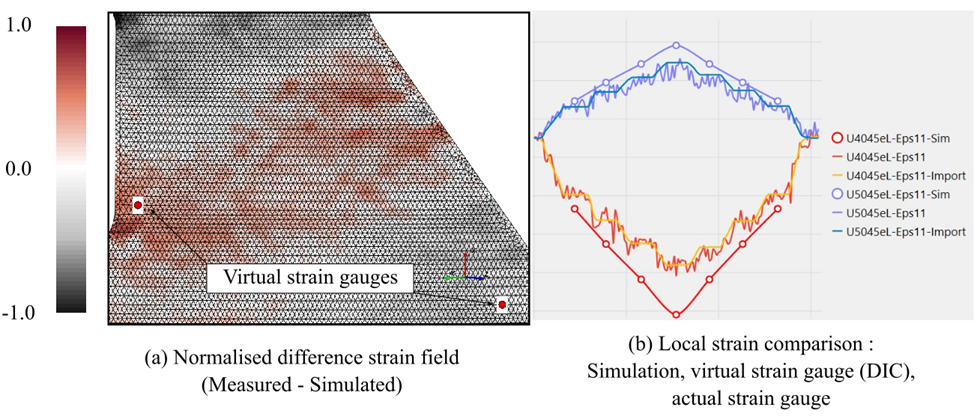
Additionally, we could use the ‘virtual strain gauge’ feature of the DIC software to compare data across three different sources in the area: simulation, DIC (virtual strain gauge), and actual strain gauge data as recorded during the training stage of clinical simulation of the test. Fig 6b presents the normalised local strain evolution during the simulation experience, the simulated setting, and successive loading steps.
A comparison of virtual gauge measurement and traditional gauge values shows that although virtual gauges provide a noisier signal (as expected following preliminary uncertainty analysis given the local element size and the chosen FOV), average strain levels are quite close for each loading step.
Second, comparing simulation previsions with experimental results, it was found that for this pair control group of gauges, the simulation was rather conservative, as higher strain levels of low fidelity simulations and high fidelity simulations than were expected in these areas.
The next step is using virtual strain gauges in areas where no physical strain gauges were present, especially in peaks in the strain difference fields. In this case, we showed that locally some strain localizations reached higher values than expected in the initial simulation, although remaining well below critical levels for structural integrity (see Figure 7). Overall credibility was thus judged satisfactory for this simulation effort.

How Ariane Group increases the credibility of simulation with DIC
DIC also makes it possible to observe the localization of deformation, which is always a high source of uncertainty when performing strain gauge measurements. “As is often done in the case of structural tests, we validated DIC measurements with strain gauges on target locations, which allows us to ensure DIC credibility and to use all the strain maps for validation purposes.” The predictive aspect of the simulation was validated by full-field comparisons: expected strain localizations are well predicted (for axial, transverse, and shear strain fields), and local differences were shown not to be significant with respect to measurement uncertainty in the most critical areas.
Engineers can now validate the whole simulation based on learning the model from hundreds of measurement points and visualize the error map between the test and the simulation based on the high-fidelity simulations used in simulation, training, and data. “It’s much more comprehensive than trying to interpret strain gauge errors,” confirms Nicolas Swiergiel. Thanks to DIC, error sources are more easily explained, and the model uncertainties are drastically reduced since CAE engineers have a larger overview of strain gradient areas.
“This also opens the way for new validation metrics that can encompass simulation experience from all measurement sources,” explains Florent Mathieu, CEO of EikoSim. “There is some ongoing research about the ideal criteria to assess the credibility of a simulation effort.”
A virtual test scene as a time-saving effort
Designing specifications for large-scale applications involving DIC in a complex industrial context can be quite challenging. It is difficult to anticipate appropriate camera positioning to guarantee that the targeted zones of interest (ZOI) will remain visible for the test duration. The use of virtual test scenes (also called virtual pre-testing), thanks to the Blender software, can help tackle these issues.
Blender is a free 3D rendering software. It makes it possible to reproduce the test setup in a virtual scene, where the user can position cameras. Virtual images corresponding to these cameras’ FOV can be rendered for initial and deformed states of the mechanical test, based on finite element simulation previsions for the test. To this end, python scripts were designed to deform the mesh node by node in Blender and to capture virtual camera images at each simulation step. Their virtual images can then be processed by DIC software, to give a realistic a priori estimate of measurement possibilities for the chosen camera positions (strain and displacement uncertainty, notably).
In the case of the Ariane 6 Galileo dispenser, several challenges need to be addressed. First, the component’s scale (approximate dimensions = 3mx2mx2m) is quite large for usual DIC setups (usually under 1m^3). Second, there was a need for simultaneous DIC monitoring at different scales, thus involving several DIC systems that needed to be synchronised along with the rest of the instrumentation. Global DIC results needed to be acquired across the whole component, to provide full-field displacement measurement displacement, and also to check that the experimental boundary conditions do not significantly deviate from the specification. These results are exploited qualitatively (no quantitative comparison to the simulation is sought). Local DIC results, however, are required for more quantitative comparisons with FE previsions. They are needed in three ZOIs of various sizes (upper and lower bracket/frame interactions, see Figure 1) where strain gradients are expected, and thus strain gauge-only instrumentation is insufficient to qualify the structure.

Test setup preview in Blender, zones of interest (ZOI)
For ZOIs n°1,2 and 3, the objective of the camera setup will be two-fold.
1 – check that the strain levels of fidelity will remain below a critical level.
2 – use the whole measured field to validate the simulation (were strain localizations accurately predicted, etc.)
Thanks to testing virtualization, EikoSim could propose camera positioning that gave FOVs compatible with validation requirements, and with the test environment and instrumentation, for the 4 camera setups. Camera locations were determined at millimetre precision, and the test rig was designed to accommodate these positions. Adapted lenses were also specified in this step. Finally, the speckle pattern size and application method were also decided thanks to virtualization. For FE-based DIC, ideally, each reprojected mesh element on the test images should contain a texture that can be analysed by the DIC algorithm (see Figure 2). Based on this requirement, it was decided that paint should be used for some smaller ZOIs (1,2,3) and painted adhesive film for the global tracking system (ZOI 4).

Additionally, the team ensured that measurement uncertainty was compatible with the validation of simulation in the most critical area (i.e., measurement uncertainty is significantly lower than the strain levels expected for the close-up shots of the structure). Figure 3 presents a normalised estimate of strain uncertainty fields for ZOIs 1 & 3, where quantitative comparisons will be needed to qualify the structure.

Using the finite element mesh provided by the ArianeGroup simulation team as a basis for our estimate of DIC measurement, it was estimated that the uncertainty strain field (standard deviation of the measured field on virtual images without displacement but with added white noise) approximately 1/5th of the expected maximum strain for the anticipated loads. Thus the camera positioning was deemed satisfactory, and the specification was validated.
How Ariane Group saves 50% of DIC preparation and analysis time with EikoSim
Optical measurement methods such as Digital Image Correlation (DIC) are known to yield high levels of high fidelity both in test scores and large quantities of measurement information and are more and more accepted in the industry as a way to get a better understanding of the outcomes of structural, mechanical tests. However, using this technology to its fullest potential, especially with multi-camera setups, requires a long and careful preparation time, plus additional laboratory time on the test day.
“On such a large structure, there are some zones we just can’t reach without preparation,” explains Nicolas Swiergiel. Especially tall structures need the design of a scaffold just for the cameras to be level with the region of interest and correctly oriented. “Doing this kind of operation after the specimen is installed is incompatible with the time frame of such a test, where everything has to be kept as fast and fluid as possible.” ArianeGroup and EikoSim decided to develop a test preparation tool dedicated to the design of DIC setups to allow themselves more freedom in the design of measurement setups. The objective was to allow the full virtual preparation of the 8-camera setup, including scaffolding, that made it possible to predict the DIC outcome fully. “We based this EikoTwin Virtual on Blender, which has all the camera handling and image generation capabilities we needed,” says Pierre Baudoin, Research Engineer at EikoSim.

EikoTwin Virtual helped prepare for the test with commercially unique features:
- 3D cameras positioned around the test scene;
- Rendering of virtual images to calculate the measurement uncertainties and validate the regions of interest with DIC;
- Confirmation of the agreement between FE mesh and measurement objective, and adaptation of the Region Of Interest;
- Creation of the test implementation map to help determine the scaffolding’s exact sizing.
“Now we’re able to fully plan where to put the cameras to optimise the measurement result, and it doesn’t take any facility time,” continues Nicolas Swiergiel. “Being effective on d-day is mandatory since schedules are extremely tight. We were happy to see the first real-life images look exactly like the first virtual reality ones”. In total, using this new solution helped save 4 days of on-site preparation for this test only, compared to the usual installation of 8 cameras, while maximising the size of the ROI.
What ambition does this platform allow you to have?
This data fusion platform now allows for a more systematic review of simulation, and fluid correlation process, which in turn makes it possible to increase the part of development that’s being made based solely on simulation models. “What we’re looking for with this project is to increase our confidence in the credibility of simulation models in the long term,” says Nicolas Swiergiel. “This will allow us to remove the largest tests from the campaigns, which we’re already trying to do now, to develop innovative simulations faster and to save approximately 25% of costs. The Virtual Testing concept is becoming concrete, and this platform is one of the key elements to achieve that goal”.
98-100 AVENUE ARISTIDE BRIAND
92120 MONTROUGE
FRANCE