Mastering self-calibration of cameras with EikoTwin DIC
- By Lucas Angénieux, Research engineer and Pierre Baudoin, R&D engineer at EikoSim
To provide accurate Digital Image Correlation (DIC) results, the EikoTwin DIC software must first calibrate the camera system. The use of the part under study as a reference allows a self-calibration of the cameras, specific to EikoTwin DIC.
This is made using images of the structure in its reference state (unloaded). Using these images, the software determines the intrinsic parameters (the camera’s focal lengths, optical centers, skews) and extrinsic parameters (camera positions and orientations in the 3D space of the simulation mesh) that characterize the camera system.
A specific feature of EikoTwin DIC is that the measurement is carried out directly in the simulation coordinate system thanks to a method called self-calibration. The principle of self-calibration is to use the nominal geometry of the component, as defined in the finite element mesh, to position and orient the camera system with respect to the 3D coordinate system of the model.
The full calibration process is shown in Figure 1 and consists of two steps: pre-calibration, which aims to initialize the projection matrices associated with each camera, and calibration, which aims to update these projection matrices and update the shape of the finite element model to account for deviations from the nominal geometry when measuring the displacement fields.
The camera’s self-calibration operation consists in solving an ill-posed inverse problem by an iterative method. Therefore, it is preferable to initialize the problem with a set of parameters fairly “close” to the final solution to ensure algorithmic robustness.
This initialization is determined by the pre-calibration step, which is therefore, a crucial step to obtain a robust calibration.
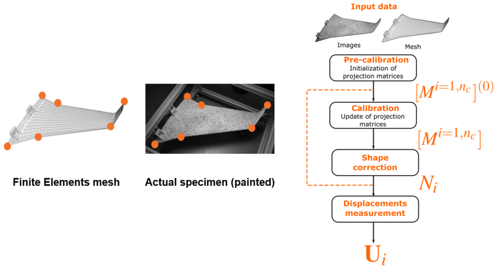
Overall, good calibration is essential to ensure the quality of data processing by the DIC algorithm. It is important to find the right intrinsic and extrinsic parameters at the end of these calibration steps. For this reason, we will look in more detail here at the procedure to follow in to ensure a robust cameras self-calibration.
Criteria for a robust camera self-calibration
Several criteria must be considered before the test is carried out to ensure accurate self-calibration with the EikoTwin DIC software.
There are 4 main principles that will have a first-order impact on the quality of the calibration:
- The “3D” distribution of the pre-calibration points in the model space. This can be quantified as the average distance between a set of 3D points and their average plane.
- The “rough” aspect of the observed surface (the surface may or may not have distinctive features that can be easily identified both on the 3D model and on the images, e.g., corners, chamfers, bolts, bores, rivets, …)
- The adequacy between the nominal geometry of the part and the real geometry (model strongly simplified geometrically or not)
- Size of the area occupied by the image pre-calibration points with respect to total image size.
We will go over these criteria in detail in the next sections. We will also provide recommendations in order to optimize the camera’s self-calibration process and thus ensure DIC measurement accuracy.
“3D” distribution of the pre-calibration points in the model space
The case of a perfectly flat surface is a degenerate case for which the conventional camera self-calibration procedure cannot be carried out (there is no uniqueness of the intrinsic and extrinsic parameters couple yielding an identical 2D reprojection of the set of 3D model points).
In this case, one should strive to use environmental elements as additional out-of-plane 3D points to constrain the pre-calibration step further. If inapplicable, the use of a hybrid calibration procedure using calibration target images in addition to the sample images can be used.
If, however, one wishes to calibrate only using the EikoTwin DIC self-calibration method, it is important to keep this 3D distribution criterion in mind. For example, these points’ availability can be confirmed before the test, using CAD or FE mesh data. One then needs to locate identifiable points on the mesh and on the images and can determine whether it is possible to obtain a point distribution as removed to a plane as possible. If such a set of points cannot be determined, we will then have to think about adding clickable points with the help of additional markers or objects in the environment.
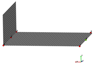
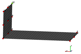
Easy selection of pre-calibration points (rough vs. smooth geometry)
The more pre-calibration points are clicked by the user, the more robust the calibration will be. It is, therefore essential to validate before the test that there will be sufficient matching points between the model and the observed region. This question can be answered simply by studying the region and its immediate environment and list all the geometric singularities that will be easily found in the images.
If 10 or more such singularities are available, the pre-calibration conditions can be considered satisfactory with respect to this criterion.
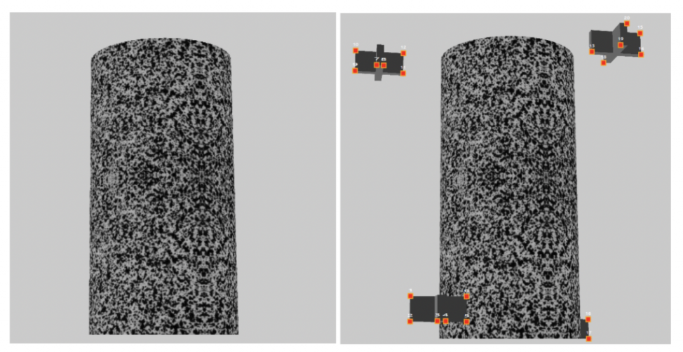
Alternatively, one can use test set-up elements whose geometry and position in 3D space of the simulation mesh would be well known in order to carry out this pre-calibration step.
This process is illustrated in Figure 3 on images of a virtual test generated with the Blender software. An article available on our blog describes in more detail the use of this software for these virtual cases.
Adequacy between nominal and actual component geometry
This point is the most delicate to characterize in generic terms in the prospect of test preparation. We can however try to assess the general adequacy between the finite element model and actual geometry by answering the following questions:
- Is the model mesh generated directly from the CAD model?
- Does the mesh use 3D elements or shell elements?
- If shell elements are used, what are the modeling assumptions?
- Are elements that are not relevant to dimensioning (inserts, mechanically unloaded connection elements, etc.) explicitly represented in the model?
The purpose of the above questions is to be able to quickly determine whether or not it will be complicated to select the 3D model coordinates of the pre-calibration points directly from the finite element model.
In short, if the mesh consists of CAD-based 3D elements, the confidence in the actual/nominal geometry match is high, and no special care is needed when selecting pre-calibration points. If, on the other hand, the mesh results from a strong simplification of the original geometry (shell elements, strong geometric simplifications), then alternative strategies for selecting pre-calibration points must be put in place.
Among them, point selection from CAD, use of 3D scanners, and request for a more realistic mesh from the calculation team can be considered.

Figure 4 – An example of a FE mesh well suited for computation (left) while containing significant geometric differences with the actual component (right). To perform calibration, a CAD-based mesh (middle) could be used to specify pre-calibration points. The component illustrated here is the Galileo dispenser A5 designed by ArianeGroup.
The wide distribution of pre-calibration points on acquired images
This point means that we use instrumentation adapted to the area observed: since the measurement accuracy is directly related to the px/mm ratio, we want this ratio to be as high as possible, and thus the region of interest to occupy a large part of the image.
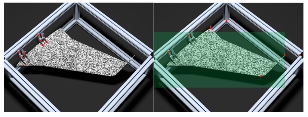
Therefore, this condition of successful pre-calibration is quite naturally respected in most tests instrumented by stereo-correlation. However, strongly elongated components may pose a problem. In this case, it may be difficult to reconcile the double constraint of filming the entire area of interest and ensuring that it takes up the most space for the images acquired.
If possible, multi-camera instrumentation can be used to bring cameras closer to the component and thus deal with the issue efficiently (example of the case of a composite bumper detailed in this blog post). It is also possible to use characteristic elements of the test environment visible on the images and whose 3D position in the finite element mesh reference frame used for the measurement is known (Figure 5).
Otherwise, to counterbalance the negative effect of the smaller proportion of the image covered by the region of interest, care should be taken to select more pre-calibration points than usual (20 or more points compared to about ten for standard cases) to ensure the robustness of the pre-calibration.
Conclusion
We saw in the previous paragraphs that it is possible to anticipate possible difficulties in the calibration process by performing a short series of verifications prior to testing. It is, therefore, possible to attempt a synthesis of the previous results using a flowchart that can be checked every time a DIC test is considered (Figure 6).

The first step, determining whether the mesh size is suitable for the measurement, involves looking at the appropriate size of the speckle pattern.
This can be done with our speckle pattern calculation worksheet, which is available free of charge on request. A best practice article dedicated to speckle pattern painting is already available on our website. A follow-up article illustrating the use of the spreadsheet will be forthcoming.
