- By Pierre Baudoin, R&D engineer ata EikoSim
Context
As part of the large-scale production monitoring of automotive parts, it is essential to ensure that the reliability of the manufactured parts remains constant throughout the part’s production cycle.
In order to make sure of this, parts are regularly sampled from production lines and tested to ensure that they still meet the required safety and endurance criteria.
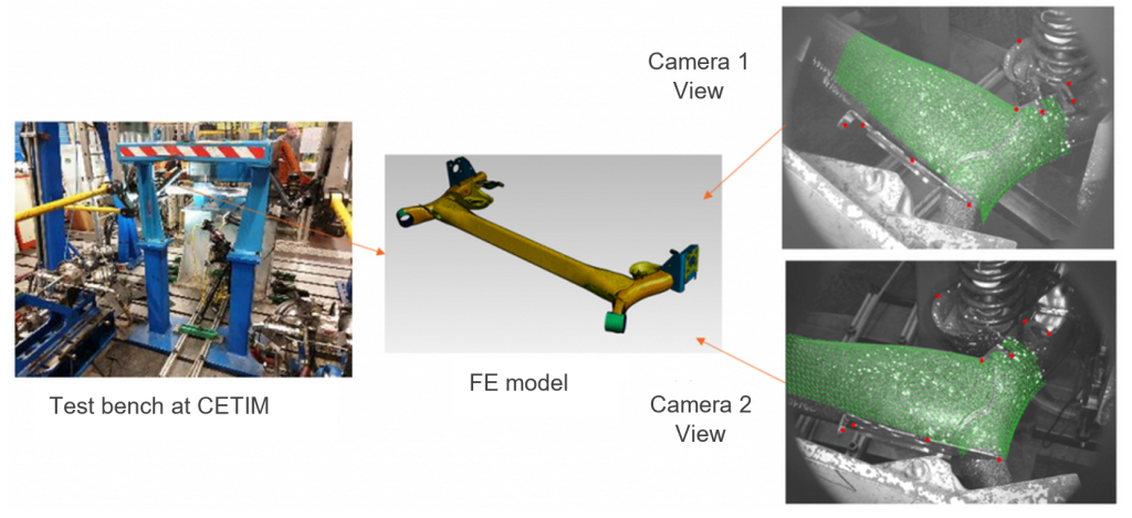
The test described in this article was carried out for this purpose and was dedicated to a vehicle’s rear axle (fig. 1).

The tested component is a rear vehicle axle, tested in multiaxial fatigue. Ahead of the test, full-scale tests are carried out on sensor-equipped vehicles driving on tracks specially designed to reproduce severe driving conditions. These preliminary tests allow us to determine typical load cycles representative of in-service loadings (turns, rough terrain, cobbles, etc.).
At the end of these preliminary tests, a solicitation sequence is extracted that we will try to reproduce on the test bench. We will then ensure that the axle can withstand a predefined number of such loading cycles on the test bench. The main criterion will be the appearance of cracks in the axle.
These cracks are currently detected by dye penetrant inspection, which involves dismounting and remounting the axle from the test bench at different stages of its theoretical lifespan (20%, 40%, …, until final rupture).
These steps of mounting and dismounting take a significant amount of time and manpower, and one of the purposes of using stereo-digital image correlation on this test was to determine whether the measured displacement fields could eventually help reduce the use of dye penetrant inspection (we have seen that with the global method, crack detection is an interesting by-product of the result measurements.)
It has already proven itself in the study of a pipe under bending stress, allowing the detection and monitoring of a crack.
Displacement field measurement with stereo DIC
Following the indications of Figure 1, we, therefore, positioned a pair of cameras opposite the axle being tested. A short video representative of a loading cycle on a rough cobbles passage and the displacement field in the vertical direction measured by digital image correlation is shown below.
In addition to this result, the measurement is expressed directly on the finite element mesh of the part, allowing an immediate comparison with the displacement fields predicted by the simulation for this loading cycle.
Results and perspectives
To this end, we imported the displacement fields computed in the SAMCEF software (fig.2), which could then be directly compared to the displacement measured by EikoTwin DIC on the instrumented area. We see that if the overall variations of the two fields are similar, the measured and calculated values differ somewhat significantly.
This is due to the application of the boundary conditions in the numerical calculation, which is idealized in relation to the actual solicitation. One way to improve the test/simulation comparison would be to re-inject the experimental boundary conditions measured in EikoTwin DIC as input of the numerical model to improve the comparability of both results.
In addition to this comparison of displacements, EikoTwin DIC’s displacement sensor creation feature could also be used to compare the measured displacement in the digital image correlation area with the theoretical input applied experimentally on the test bench through the hydraulic actuators (right in figure 2). Again, it can be validated that the values and evolution of displacement measured by digital image correlation are consistent with theoretical values. To illustrate the quantity of information amassed in the obtained results, there are 1300 displacement sensors (corresponding to the nodes of the measuring mesh) recording over 1200 moments of the movement of the piece.
In conclusion, a large amount of kinematic data can be extracted from this first test, and measured displacement can be used as new input boundary conditions in the finite element model, to improve test/simulation comparison and, in the long run, improve the predictability of simulation for this fatigue loading.
