- By Philippe Brammer, R&D engineer at EikoSim
EikoTwin DIC to validate your test kinematics, with MCE-5 DEVELOPMENT and MECATEST
The purpose of a mechanical test is to submit a part or an assembly of parts to a specific stress in order to evaluate its elementary or in-service performances. The strong hypothesis, strengthened by theory or numerical simulation, is that the test bench exactly applies this stress.
Despite the many precautions taken by the operators, the actual test bench behaviour may differ significantly from the expected result, for example due to misalignments or clearances in the assembly. Knowledge of the effective kinematics of a mechanical test can avoid long questions about the inconsistency of the results and ensures optimal use of the test data.
Structural test with imaging on a gearwheel
Let’s take the case of a test on a gearwheel carried out in partnership with MCE-5 DEVELOPMENT and MECATEST. In this test bench, the wheel is free to rotate on its axis, and a vertical displacement is applied to the upper plate which is in contact with the third tooth of the wheel. The first tooth of the wheel is in contact with the lower plate, and the stress is measured at the wheel axis. At two different angles, a pair of cameras observe the useful area that has previously been texturized or speckled. The applied stress is a gradual load-unload cycle, and one image is retained for each step.

Analysis of the test kinematics with EikoTwin DIC
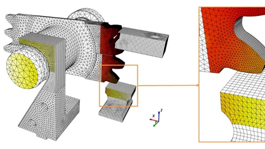
The images from each camera and a finite element mesh representative of the test bench are loaded into EikoTwin DIC. The regions of interest of the study being the wheel teeth, the upper and lower plates and the wheel axis, the corresponding parts in the mesh are selected via the interface to define the measurement area.
In order to position each camera in the virtual 3D space of the mesh, calibration points are defined via the interface, in 2D on the first image of the camera and in 3D on the mesh. EikoTwin DIC exploits these points and provides the user with a visual projection of the measurement area on the first image of each camera.
Using its digital image correlation algorithm that compares images for each loading step, EikoTwin DIC computes and displays displacements and strains on the mesh of the measurement area for each loading step. These fields can be analyzed as they are, compared to simulation results via the interface and also exported for external use.
The displacement fields analysis via the EikoTwin DIC interface allows the actual kinematics of the test to be quantified and relevant conclusions to be drawn such as low axis displacement, naturally heterogeneous deformation of the first tooth of the wheel and slight pivoting of the lower plate.
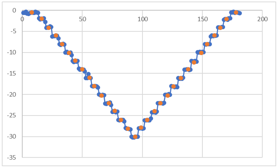
EikoTwin DIC also makes it possible to create numerical displacement sensor and strain gauge and to plot the evolution of their values over time or as a function of the applied stress. For example, the creation of a numerical displacement sensor at the endpoint of the first tooth of the wheel leads to the conclusion that the loaded and unloaded displacement paths coincide, and that the minimum and maximum load positions during a cyclic loading are constant.
Contribution of EikoTwin DIC in the exploitation of the test
In the context of controlling the test kinematics, EikoTwin DIC makes it possible to know the displacement at any point of the measurement area for each loading step, and thus to evaluate the proper conduct of the test in comparison with the desired behaviour. The main richness of the results obtained lies in its availability over the entire measurement area, and its definition on the same mesh as that used for numerical simulations, which will allow a direct comparison and a use in structure computation.

