- By Florent Mathieu, Ceo of EikoSim
- Philippe Brammer R&D engineer at EikoSim
- Ludovic Barrière, Project Leader: LASER – IRT Saint-Exupéry
Why use Digital Image Correlation when testing lattice structures? This is what this article is about.
Interest in lattice structures is growing rapidly for the development of aeronautical and space components in particular. In addition to the significant mass gains they allow to consider, they offer the possibility of optimising their behaviour based on their constituent patterns.
The strong growth of metallic additive manufacturing technologies allows manufacturing parts composed of lattice structures with materials known for their mechanical performance, such as nickel-based alloys, titanium alloys or new generations of aluminum alloys. These promising architectural materials are still not widely used in the design of structural parts, as they require new development methods on a commercial scale (simulation, characterization, manufacturing).
In this context, the Institut de Recherche Technologique (IRT) Saint Exupéry, based on the experience of the SIMaP laboratory in the field of architectural materials, is conducting a 24-month research and development project called LASER (Lattice Structures for Engines and LauncheRs), bringing together major aerospace manufacturers with the aim of providing them with understanding and design tools for research departments. EikoSim, a young company specializing in the link between tests and simulations, provides the LASER project with its expertise and its software for field measurement using digital image correlation. Focus on test and simulation methods.
Tests on lattice structures carried out as part of the LASER project aim to highlight the strain modes in compression or shear configurations, with different boundary conditions and scale effects, playing on the number of unit cells constituting the specimens. The diversity of these configurations should allow the development and validation of a numerical modelling approach.
At that time, the study is limited to quasi-static stresses at room temperature as a starting point for fixing the methods. The structures tested are made of microbeams with a maximum diameter of 1 mm organized according to BCC lattice (Body-Centered Cubic) or BCCZ lattice (Body-Centered Cubic with vertical beams).

Application of digital image correlation to tests on lattice structure obtained by additive manufacturing
It is impossible to use a traditional measurement method to capture the complex kinematics of such lattice structures under mechanical stress. Strain gauges, for instance, are very difficult to use at the microbeam scale and would only provide very partial results on the structural response.
The measurement of the global displacement is still possible with extensometers and the applied stress is captured by an essential load cell.
In this context, the link between experimental results and modelling remains weak, and it seems very difficult to develop a predictive model, which will make possible the design of more complex structures with a high level of confidence, different from those characterized in the laboratory.
The use of more efficient measurement methods is one way to meet the challenges posed by these new geometries. Field measurement, particularly by digital image correlation, is a natural candidate for capturing the heterogeneity of strain and the phenomena of local instabilities that occur in lattice structures.
Compression test instrumented by image correlation
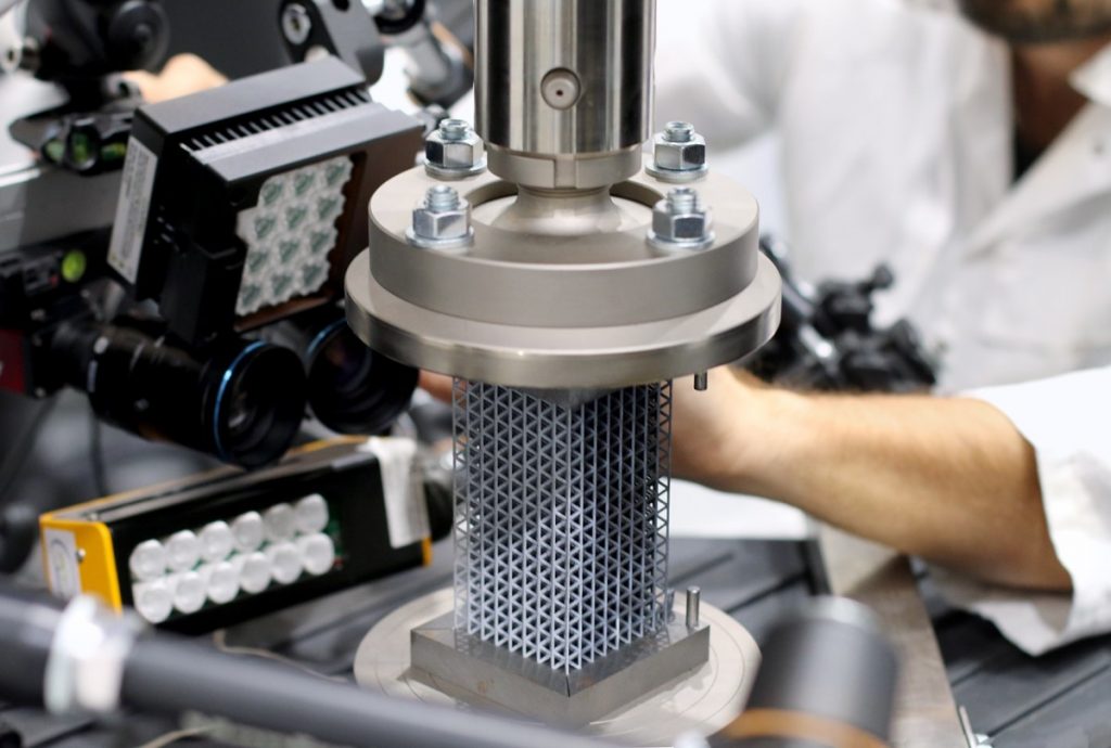
The implementation of digital image correlation on lattice structures (or any structure) involves the application of a speckle (contrasted pattern) on the part, adapted to the scale and the resolution of the camera. On lattice structures, it is applied with an airbrush to reach spots sizes of a few tens of microns.
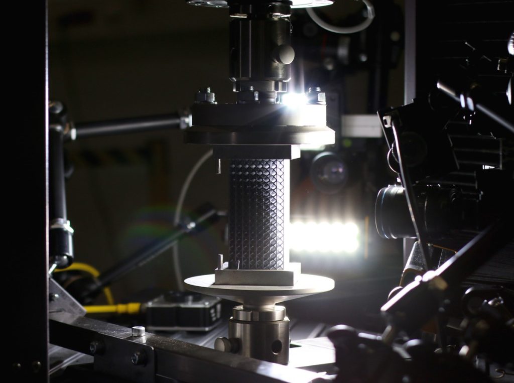
During the test, two sides of the sample are observed using two pairs of high-resolution cameras. This makes it possible to capture for sure the characteristic strain mode which results in the shear belt and all the complexity of kinematics.
From a measurement point of view, this can make the treatment process complex. With an approach based on a finite element mesh, as proposed in the EikoTwin DIC software, the measurement result is directly associated with a point in the 3D space of the model part.
There is no analytical limit to the number of cameras, which contributes to the measurement of the displacement of points that are in their respective fields of view.
Digital image correlation (or DIC) is a technique that tracks the movement of points of the lattice structures by assuming that they maintain the same grey level in the image.
Lighting conditions must therefore be controlled to limit measurement uncertainty and ensure the ability to track the structure even in large displacements.
Modeling and Computation
Several modelling approaches of the mechanical behaviour of lattice structures can be considered. The most accurate in terms of geometric representation describes each in volume microbeam.
The discretization by volume finite elements allows for staying as close as possible to the geometry as designed initially. From a physical point of view, given the strain level expected during the compression tests, it is important to describe the elastoplastic behaviour of the structure’s components.
At this point, one difficulty is describing the local mechanical behaviour by an adapted law. Several approaches are possible in research department:
- As a first approach, it is possible to consider the properties of the constituent material from standard tests. In this case, it is recommended at least that the standard tests have been carried out on specimens machined from raw materials obtained by the same additive manufacturing process as that of lattice structures.
- A second approach, proposed and implemented in the LASER project, consists in characterizing the constituent elements of a lattice structure, namely microbeams. Specimen geometries have been designed and manufactured on the same trays as the lattice structures to access the intrinsic properties of the microbeams according to their orientation (vertical, tilted). The advantage of this approach is that it allows viewing effects related in particular to the fineness of the geometry, which are relatively well known in additive manufacturing: roughness, shape error (average diameter, cylindricity), thermal history and particular metallurgy.
The application of loading and boundary conditions is an essential part of the modelling. Just as the differences between the geometry as designed and manufactured, the differences between the “ideal” load and that actually experienced by the structure can significantly impact the response.
However, measurements of these gaps are rarely available for research departments. The modelling chosen at first, therefore, largely neglects them.
The problem of computation time emerges quite quickly for this type of non-linear models, composed of millions of elements. The LASER project is currently working on a simplified approach based on an approximation of the geometry by linear finite elements with beam kinematics and with the objective of not deteriorating the accuracy of the simulations.
Test – Simulation comparison
The comparison between measurements and simulation results is often a challenge in itself. The ability to measure displacements on a point cloud is interesting, but it creates new problems when compared to the simulation.
With the approach implemented in the EikoTwin DIC software, based on finite elements, the displacement field is measured directly on the numerical simulation mesh in the same 3D reference frame. Errors related to the projection of the measurement fields on the mesh, or vice versa, are thus avoided. It also saves time for the user.
For example, it is possible to directly visualize a difference between the ideal loading path and the one applied to the part in order to correct the simulation model accordingly.
Outlook
The next step: modifying initial simulations using measurement results. These tests teach us a lot about lattice structures, so we want to use these results to improve our simulations and better understand the sources of error. Initially, the displacements measured at the edges can be used as boundary conditions for the simulation.
Then, coupled with the comparison between experimental and simulated stress-displacement curves, this approach will allow the implementation of a reverse identification strategy to refine the model parameters and reduce the test-simulation gap. The EikoTwin Digital Twin software proposes to integrate these two essential steps into a single environment. This will allow us to consider the transfer of these methodologies to the research department in the very short term and to develop the potential of lattice structures for industrial applications.
Credits
The Institut de Recherche Technologique (IRT) Saint-Exupéry* is an accelerator of science, technological research, and transfer to the aeronautics, space, and embedded systems industries for the development of innovative solutions that are safe, robust, certifiable, and sustainable. The IRT Saint-Exupéry offers on its sites in Toulouse, Bordeaux, Sophia Antipolis, and Montreal an integrated collaborative environment composed of engineers, researchers, experts, and doctoral students from industrial and academic environments for research projects and R&T services supported by technological platforms in four key areas: high-performance multifunctional materials, more electrical aircraft, intelligent systems & communications and systems engineering & modelling.
* The IRT Saint-Exupéry is a technological research institute labelled by the French government as part of the Programme d’Investissement d’Avenir (PIA).
* EikoSim is a software company specialized in test-simulation dialogue, which relies in particular on innovative measurement tools by digital image correlation, that can directly be applied to lattice structures.
The LASER project is owned by the IRT Saint-Exupéry, 50% financed by its industrial members and 50% by the French government’s Programme d’Investissement d’Avenir (PIA). It is part of the inter-IRT “LATTICES” initiative, which defines the close collaboration with the DSL (Durabilité des Structures Lattices) project led by IRT SystemX and with the Centre National d’Etudes Spatiales (CNES).

