- By Renaud Gras, Co founder – CTO of EikoSim
Need to perform a correlation between an Abaqus simulation model and measurements automatically?
Whether it is by developing a Python script, actually using the C++ API or developing our parsers, we have experimented a lot with reading and writing formats related to this solver, whether it is to correlate displacement or deformation fields or simply strain gauge results or load cells—review of Abaqus’ strengths and challenges, starting with some background for our particular case.
Discovering Abaqus modelling via research
Unlike many students, our encounter with the Abaqus model was not via the CAE interface but directly using the command line solver via INP files generated by an external script.
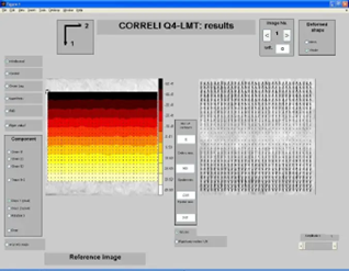
For this work, which started in 2009, it was necessary to create these Abaqus models from the global image correlation meshes created by the Correli-Q4 software to allow a perfect match between measurement and simulation. We then proceeded to identify the position of the tip by determining which single simulation part was the closest to the measurement result.

The interface of the Correli-Q4 software was developed at the Laboratory of Mechanics and Technology (now LMPS).
In this framework analysis, we were not yet making identification analyses with inverse methods, but we can describe the procedure as follows:
- Creation with Matlab/Python of a series of models in INP files, thanks to the basic parameters: initial image correlation mesh, split by a crack represented by a simple opening or by cohesive elements. The position of the tip is configurable. Managing the connectivity table is a real challenge, especially if you want to extrude a 3D mesh!
- Launching the calculations in the command line;
- Extraction of the displacement fields from the ODB via a Python script;
- Comparison of the measured and simulated fields to determine the crack tip.
Later, as image correlation adopts unstructured meshes, we will start reading meshes from an INP file and add a feedback loop for material property identification.
This is our transition to finite element mesh parsing, with a limited number of exceptions, as all our INP files are exported from Abaqus CAE and thus written in a very similar way.
Adaptation to industrial cases
The creation of EikoSim and our engineering software was an opportunity to re-discover finite element analysis and data manipulation and to understand why our customers could not take the time to develop their own integration: making a versatile and reasonably generic connector is much more complicated than laboratory work.
There are several reasons for this:
- Industrial needs are more varied and cover much of Abaqus’s functionality. In the lab, we did not need to integrate material laws in the form of UMATs, material orientations, exotic element types, boundary conditions… The discovery of these needs forced us to prioritize the developments.
- INP files can be exported by other pre/post than Abaqus CAE. Abaqus being quite open to other forms of syntax for these files (for example, in the order of definition of PART/INSTANCES), we have to be able to parse these format variants ourselves or decide to impose a unique syntax on our customers, even if it means asking them to re-write the INP file. Difficult choice!
- Not only do we have to read an INP file, but we also have to rewrite it in a version “enhanced” by our Digital Twin. This means that many functionalities that we do not need to interpret for the needs of the measurement must still be kept in order to be rewritten as they are and in the right place in the output INP file. And for those that are interpreted and need to be replaced in the model, we also need to be able to identify the block in the INP file that needs to be replaced and write the new block generated by the EikoTwin software suite.
So, what did we choose to do?
Because of the previous considerations and our past experience, the use of Python scripts did not seem to us to be adapted for a sufficiently versatile integration model.
Two options were then available to us thanks to the API available in the Abaqus software distribution, either to use the Python API or to use the C++ API. We naturally chose the C++ API, because our software code is also in C++, but also for performance reasons.
In order to meet the needs of the EikoTwin software suite, which is to perform analysis of the correlation analyses with the Abaqus simulation model, we must be able to :
- to read in the INP input file the finite element mesh, the material orientations assigned to each element in order to be able to express the deformations in this local reference frame, the boundary conditions, the materials, and the calculation steps;
- to rewrite the modified INP file;
- to read the simulation results contained in the odb file;
- to rewrite an odb file.
First, the fact that we have to read an input file and a result file implies that we have to be able to assign these results to the nodes and elements of the internal mesh format used in our software.
Therefore, it is critical to maintain the information of the original node and element numbers read into the INP.
Secondly, having to modify the model and rewrite it requires storing the structure and information of the input file.
For this, we used a storage tree that allows us to modify nodes of this tree and to be able to rewrite what has not been modified simply.
Other technical needs are added to this; in particular, we need to be able to :
- distribute our software suite without explicitly linking it to Abaqus, but that the final client be able to use our C++ API overlay with its Abaqus installation;
- manage different versions of Abaqus present at our customers’ sites;
- manage other solvers later on (and in particular formats linked to Hyperworks, Samcef…).
Abaqus integration architecture diagram
The advantage of using the C++ wrapper coded by us is that we can compile a static library for each version of Abaqus.
This allows us to determine at runtime which version of Abaqus the client is using and to use the dlls of his installation.
What does the result look like?
After a few years of development and many lines of code, our integration with Abaqus via its APIs and our parser tools is still perfectible but has already solved many customer cases.
Among the latest developments, the driving of sensitivity studies in Abaqus allows users to use the solver as a “black box” and to estimate which model parameters can be identified on a given test.
The figure below summarizes the connections already possible.
Next steps on the roadmap for a better correlation to your Abaqus simulation?
The connection to simulation servers (a challenge: they are usually under Linux, and our software is Windows-only) and the adequate use of shell elements for the DIC and the test/simulation comparison, which are essential for large structure simulations.

