Verification of the robustness of an Image Correlation software – a collaboration with SAMWELL Testing Inc.
The quality of displacement fields measurements using digital image correlation depends on many factors which can be:
- Internal to the software (implementation of the algorithm, shape functions used for describing displacements, image interpolation method…);
- External to the software (quality of the speckle pattern, resolution of cameras, quality of calibration, …)
In order to validate the robustness of a digital image correlation software algorithm, it is interesting to compare the results of the software with other reference measurements obtained independently but under identical test conditions (same external factors to the software).
The comparison can be made over the entire displacement field with another digital image correlation software or in a localized area with a physical sensor.
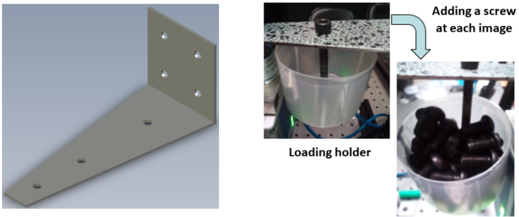
To compare EikoTwin DIC results with other gauges, a test has been run in the Samwell Testing Inc. test lab. This test involved studying the bending of a cantilever slab screwed on a rigid support. The loading is applied on the center hole and is incremented by 7.8g at each new image (see Figure 1).
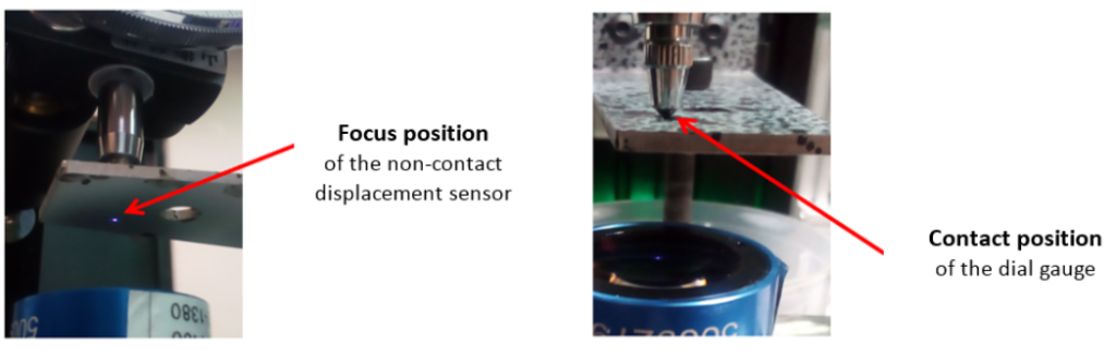
The test was instrumented with a stereo-correlation digital image device with two 12 MP cameras (4000×3000 resolution). It was also instrumented with a dial gauge and a non-contact displacement sensor measuring the displacements at the same position (see Figure 2).
In order to be able to compare all the results, it is necessary to create both digital image correlation software numerical sensors at the same position as the two physical sensors (see Figure 3).
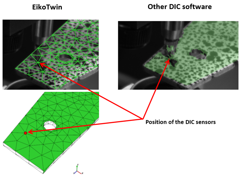
After post-processing images with both software, the normal displacement to the surface of the part measured at the location of the fictive sensors was exported.
The displacements measured during the test by the two physical and DIC sensors can now be compared (see Figure 4).
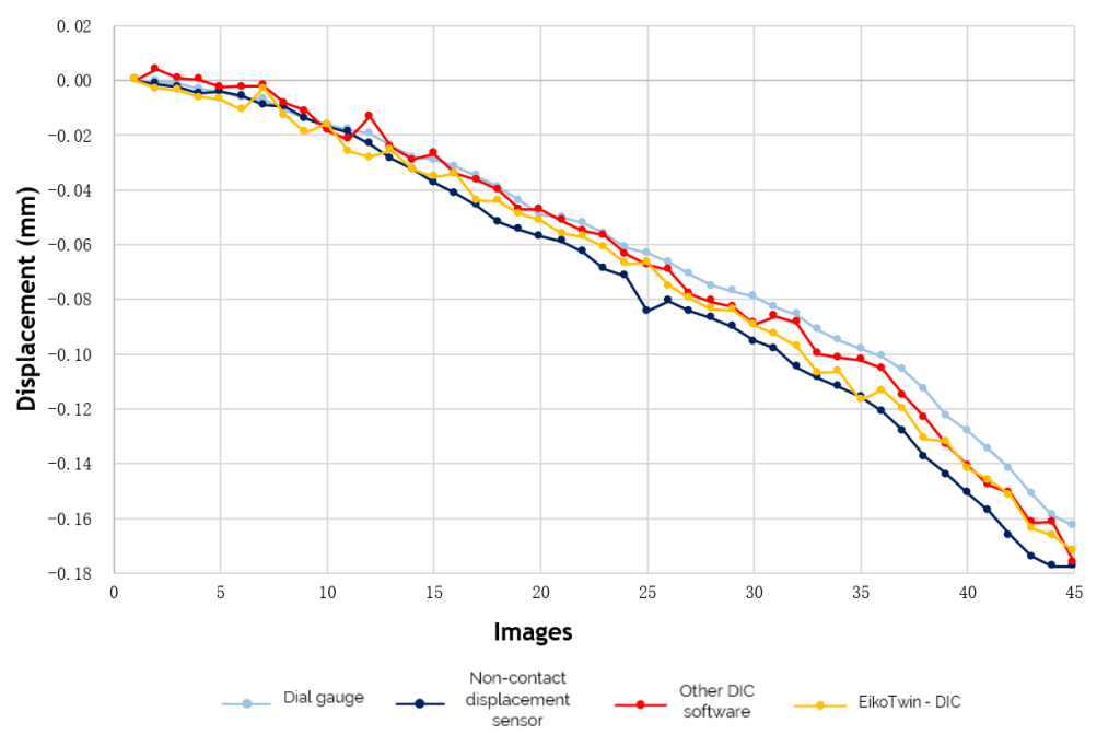
The displacement results obtained with the EikoTwin DIC software are surrounded by the results obtained by the two physical sensors. This confirms the robustness of the algorithm used in the EikoTwin DIC software for this test. The maximum deviation measured in normal displacement of the EikoTwin DIC software with the reference software is 15 μm, with the non-contact displacement sensor 18 μm and with the dial gauge 19 μm.
The next step in this study could be a comparison with simulation. Since the results are measured directly on the FE mesh with the EikoTwin DIC software, this comparison will be much faster and easier to achieve than with standard stereo-correlation software.
In this case, a tedious post-processing step involving frame coordinate system transformation of the measured displacements would be necessary.
In addition, by using EikoTwin DIC combined with physical sensors, the sensors repositioning relative to the mesh will be easier than using traditional image correlation software (see Figure 4). Finally, the simulation model can be updated using the measurement obtained with the EikoTwin Digital Twin software.
To further validate the software’s robustness, other more complex tests could be conducted (multiaxial loading, large displacements, dynamic loading, etc.). Similarly, the comparison could also be extended to strain fields, by comparing the values measured by Digital Image Correlation with the values measured by a strain gauge, in order to compare software performances for this second metric.


98-100 AVENUE ARISTIDE BRIAND
92120 MONTROUGE
FRANCE