![]()
- By Floriane Soulas, R&D engineer at EikoSim
In a previous article, we discussed how to choose the size of the speckle pattern for your experiment. We introduced the necessary parameters to control in order to optimize the size of your speckle for each of your tests. As mentioned, although the quality of a speckle pattern can only be analysed with respect to the intended application, there are 3 main parameters to take into account. They can give you information about the quality of your texture, and if necessary, you can play with them to achieve the best speckle possible.
These three parameters to compute speckle pattern size are:
- The size of the observed area: make spots of adapted diameter according to whether your zone of observation is 10 mm or 1 m wide. We recommend spots with a minimum diameter of 4 pixels.
- The size of camera sensors: This dimension defines the “physical pixel size”, or pixel/millimeter correspondence, that depends on your hardware and the lens used.
- The physical size of the elements used: The size of your finite elements must be adapted to the sought application and to the size of the speckle pattern. We consider that each element must contain at least 3 to 4 spots of speckle. It is possible to either adapt your speckle pattern to your FE model or either adapt the size of your FE mesh to the speckle you made.
Need some help ?
To help you compromise between these parameters and to help you find the ideal size of the speckle spots before your experiments, EikoSim provides a simple spreadsheet that we use to prepare the tests. When coupled with Blender, it also allows you to test several configurations before the day of the test. It is then easier to carry out the test serenely and to ensure that you can optimally process the images you will acquire. The spreadsheet is presented as follows.
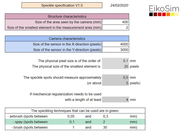
The first part, to be completed by the user, includes:
- The camera characteristics: sensor size (in pixels).
- The characteristics of the studied structure: sizes of the observed area and of the smallest elements of the FE mesh.
Depending on the completed values, the “results” section will automatically provide:
- The pixel/millimeter correspondence of the camera sensor.
- The size in pixels of the FE elements.
- And consequently, an adapted size for the speckle spots (in pixels and millimeters).
Moreover, the last box gives some speckling techniques that can be used according to the recommended spot size. It provides the minimum and maximum sizes of spots to be carried out with these methods. There are three methods available: airbrush, spray, and brush.
Not good enough ?
Finally, if you cannot modify your FE meshes it seems so refined for the measurement, it is possible with EikoTwin-DIC to compensate for this problem. You can make up for the difference between the optimal and real size of the spots by adding mechanical regularization. This technique is useful in cases where the mesh elements are too small with respect to the image, which implies insufficient information in each element. It applies a new characteristic length to the problem, corresponding to the ideal size that our meshes should have. Mechanical regularization allows to link the elements together by averaging the results around this new characteristic length.
You are now ready to optimize your test preparation and your speckle pattern and get the most out of your campaigns!
Update of the 20/11/2020 :
- The physical size of a pixel is now calculated from both the width and the height of the area viewed by the camera ;
- Now the spreadsheets provides an allowable range for the size of speckle spots ;
- The calculation of the regularization length has been improved.
![]()